
Connector

a technology of connecting rods and connectors, applied in the direction of connecting rods, electrical appliances, coupling devices, etc., can solve the problems of unfavorable situation, increase the height of the connector by a thickness of the ceiling wall, etc., and achieve excellent shape stability, avoid the effect of enlargement of the connector, simplify the configuration of the slider

Active Publication Date: 2016-03-17
SUMITOMO WIRING SYST LTD
View PDF5 Cites 3 Cited by
  • Summary
  • Abstract
  • Description
  • Claims
  • Application Information

AI Technical Summary

Benefits of technology

The invention relates to a connection holder for holding a slider in a lock arm. The technical effects of the invention include: (a) the connector does not require a dedicated space for the base portion, which avoids enlarging the connector; (b) the slider does not require a dedicated guide structure for guiding its movement, simplifying its design; (c) the slider is formed into a frame shape, ensuring its shape stability and protecting the initial position holding portion from damage; (d) the connection position holding receiving portion is designed to prevent accidental release of the connection state.

Problems solved by technology

In the above case, since the ceiling wall is arranged to cover the slider from above, there is a problem of increasing a height of the connector by a thickness of the ceiling wall.
This is an unfavorable situation.

Method used


Image

  • Connector
  • Connector
  • Connector

Examples


Embodiment Construction

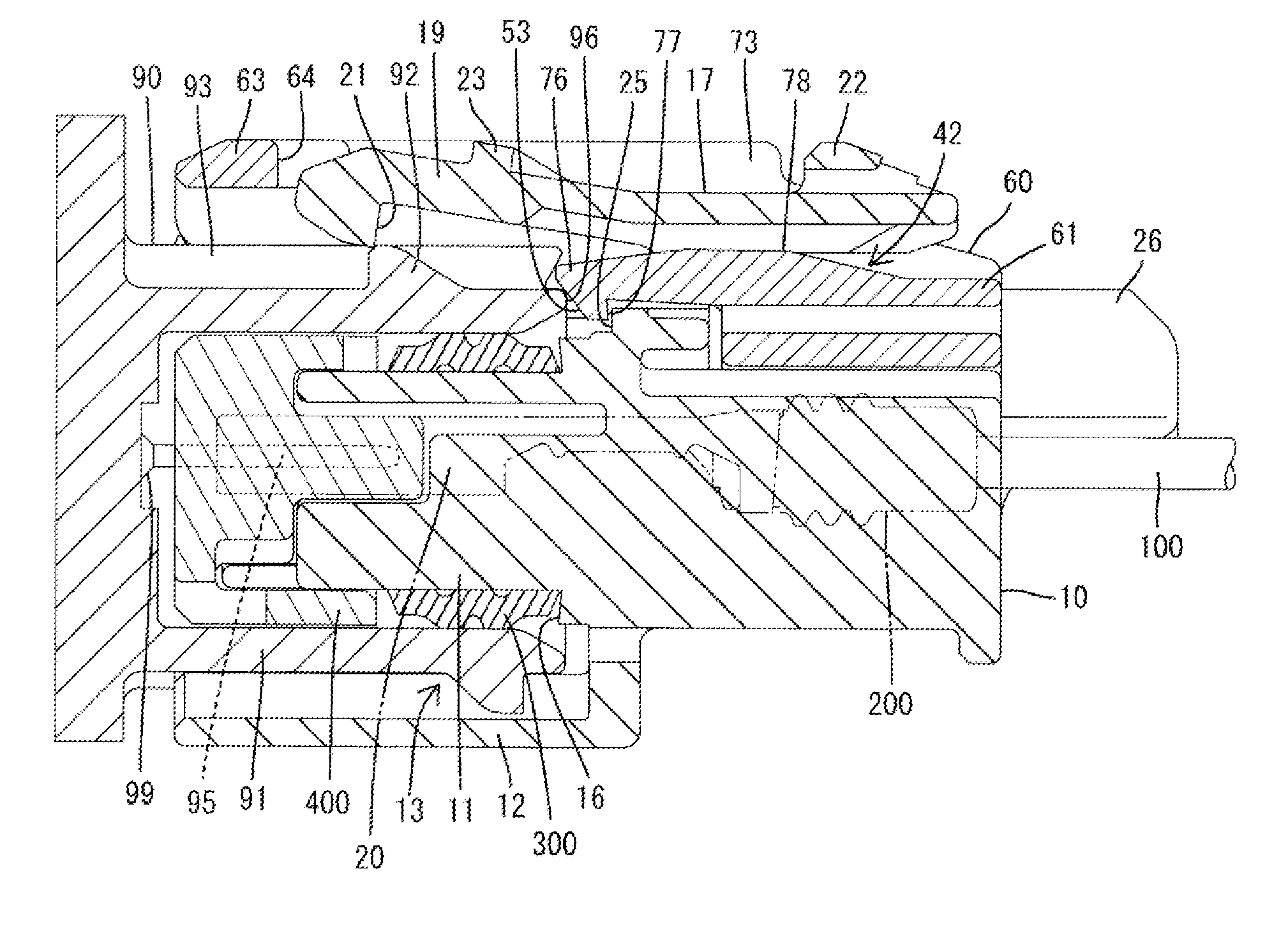
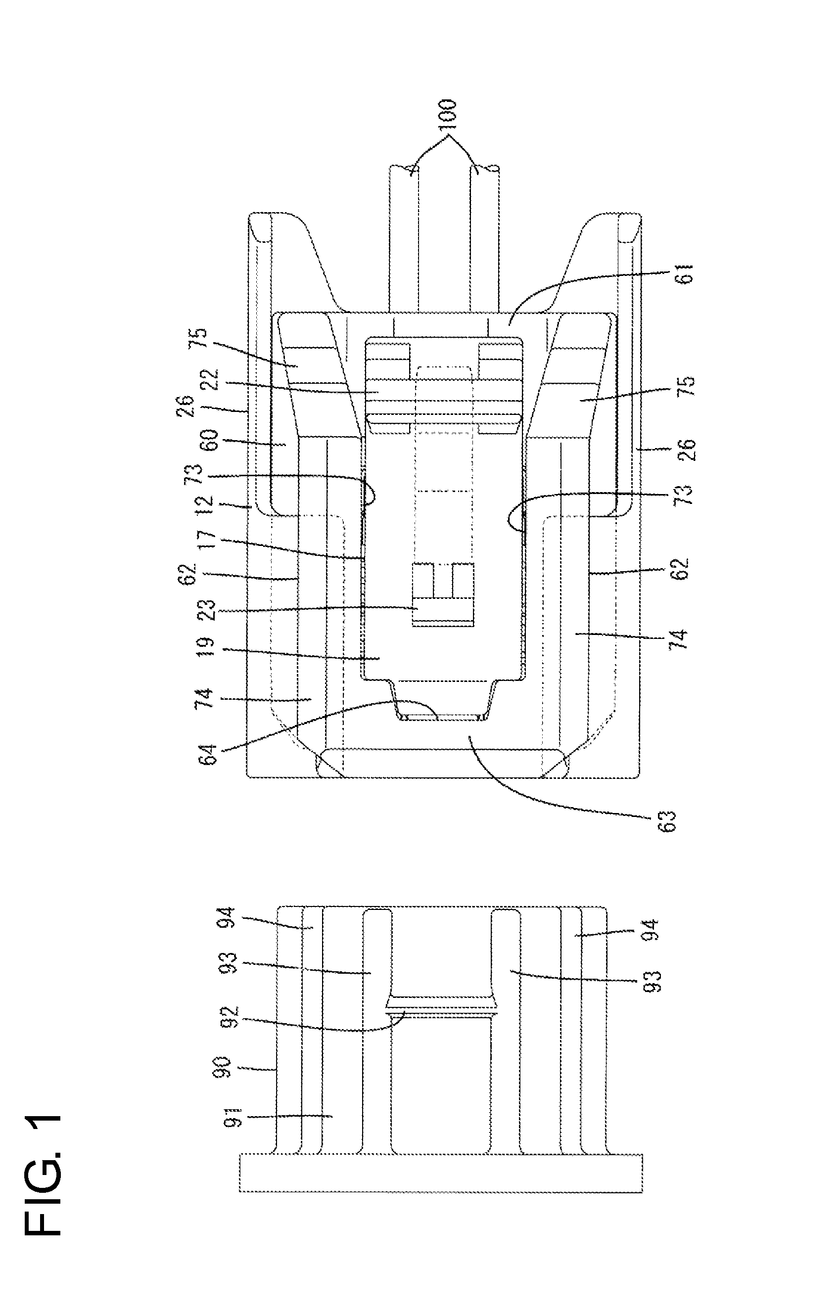
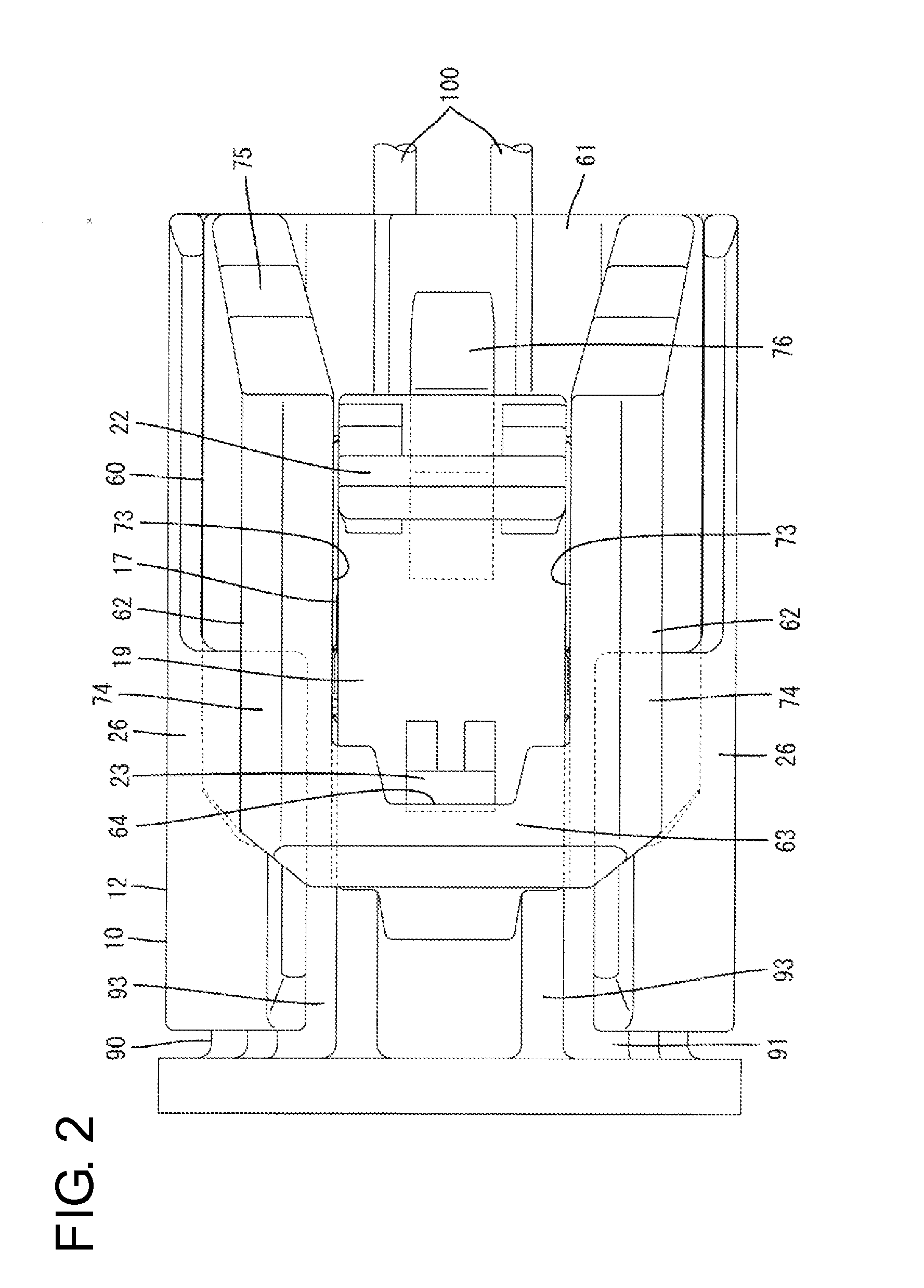
[0026]One embodiment of the present invention is described with reference to FIGS. 1 to 12. This embodiment includes first and second housings 10, 90 connectable to each other, a slider 60 to be assembled with the first housing 10, spring members 80 to be assembled with the slider 60, first terminal fittings 20 to be mounted into the first housing 10 and second terminal fittings 99 to be mounted into the second housing 90. Note that, in the following description, connection surface sides of the first and second housings 10, 90 are referred to as front sides concerning a front-back direction and a vertical direction is based on FIG. 3.

[0027]The second housing 90 is made of synthetic resin and includes, as shown in FIG. 3, a tubular receptacle 91. Tabs 95 of the second terminal fittings 99 are arranged to project into the receptacle 91. A lock portion 92 is provided to project on the upper surface of the upper wall of the receptacle 91. Further, as shown in FIG. 1, a pair of guide pro...


PUM


Abstract

A connector has a slider (60) with a base (61) extending along a width direction and to be inserted below a lock arm (17). Two arms (62) project from opposite widthwise ends of the base (61). A coupling (63) couples projecting end parts of the arms (62) and faces an upper surface side of the lock arm (17). A deflectable initial position holding portion (76) is provided on the base (61) and is configured to regulate a movement of the slider (60) to a connection position by resiliently locking an initial position holding receiving portion (25) of a housing main body (11) at an initial position. A connection position holding portion (64) is provided on the coupling (63) and is configured to regulate a detachment of the slider (60) by contacting a connection position holding receiving portion (23) of the lock arm (17) at the connection position.

Description

BACKGROUND[0001]1. Field of the Invention[0002]The present invention relates to a connector.[0003]2. Description of the Related Art[0004]A connector disclosed in Japanese Unexamined Patent Publication No. 2002-184526 includes first and second housings connectable to each other (called “male and female connectors” in Japanese Unexamined Patent Publication No. 2002-184526) and a slider (called a “front slider and a rear slider” in Japanese Unexamined Patent Publication No. 2002-184526) movably assembled with the first housing. A coil spring is incorporated into the slider. When a connecting operation is stopped in the process of connecting the first and second housings, a spring force of the coil spring accumulated thus far is released and the first and second housings are moved and biased in directions separating from each other, thereby preventing the first and second housings from being left in an incompletely connected state.[0005]Further, the first housing includes a tubular rece...

Claims


Application Information

Patent Timeline
Patent Type & Authority Applications(United States)
IPC IPC(8): H01R13/627
CPCH01R13/6272H01R13/639H01R13/641
Inventor NAKASHIMA, AKIRAHASHIMOTO, NORIHITOKATAOKA, SHIGETOTANIKAWA, NAOTAKANAKAMURA, HIDETO
Owner SUMITOMO WIRING SYST LTD
Learn More