Electric connector for wiring harness having a short circuit terminal

a technology of short circuit terminal and electric connector, which is applied in the direction of securing/insulating coupling contact members, coupling device connections, electric discharge lamps, etc., can solve problems such as gas generator malfunction, and achieve the effect of preventing the expansion of the connector

Active Publication Date: 2007-10-02
YAZAKI CORP
View PDF1 Cites 19 Cited by
  • Summary
  • Abstract
  • Description
  • Claims
  • Application Information

AI Technical Summary

Benefits of technology

[0010]It is therefore an objective of the present invention to solve the above problem and to provide a connector including a short circuit terminal that electrically connects the two terminal fittings to each other when the coupling of the connector and the mating connector is removed, thereby preventing the connector from being enlarged, and to provide a connector unit including such a connector.
[0016]With the construction described above, since the resilient contacting piece of the short circuit terminal is arranged in the bending space of the locking piece, therefore it is not necessary to provide an exclusive space for the resilient contacting piece within the connector housing and therefore, the connector can be made compact.
[0018]With the construction described above, the connection between the two terminal fittings attained by the short circuit terminal can be removed when the connectors are coupled with each other only by providing the mating connector with a portion for parting the resilient contacting piece from the terminal fitting. Therefore, it is possible to restrict force that presses the connectors in a direction in which the connectors approach each other when the connectors are coupled with each other. Therefore, the connector can be easily coupled with the mating connector.
[0019]Preferably, the connector further includes a spacer which is detachable from the connector housing and prevents the terminal fitting from coming out from the terminal-receiving chamber when the spacer is attached to the connector housing,wherein the spacer includes a restricting part for restricting resilient deformation of the locking piece when the restricting part is attached to the connector housing,wherein the restricting part is provided with a through hole which passes the resilient contacting piece therethrough and allows the resilient contacting piece to come in contact with the one terminal fitting.
[0020]With the construction described above, since the restricting part of the spacer is provided with the through hole which passes the resilient contacting piece therethrough, therefore interference between the restricting part and the short circuit terminal can be prevented from occurring and the connector can be prevented from being enlarged.
[0022]With the construction described above, a space for providing the terminal fittings can be made small in comparison with a case in which the short circuit terminal is arranged at a position where the short circuit terminal overlaps with the two terminal fittings. Therefore, the connector can be prevented from being enlarged.

Problems solved by technology

When the connector is disconnected from the mating connector, for example, for subjecting the air bag to the maintenance thereof, static electricity might be undesirably supplied to the gas generator to cause malfunction of the gas generator.

Method used


Image

  • Electric connector for wiring harness having a short circuit terminal
  • Electric connector for wiring harness having a short circuit terminal
  • Electric connector for wiring harness having a short circuit terminal

Examples


Embodiment Construction

[0052]In the following, the preferred embodiments of the present invention will be explained with reference to the attached drawings.

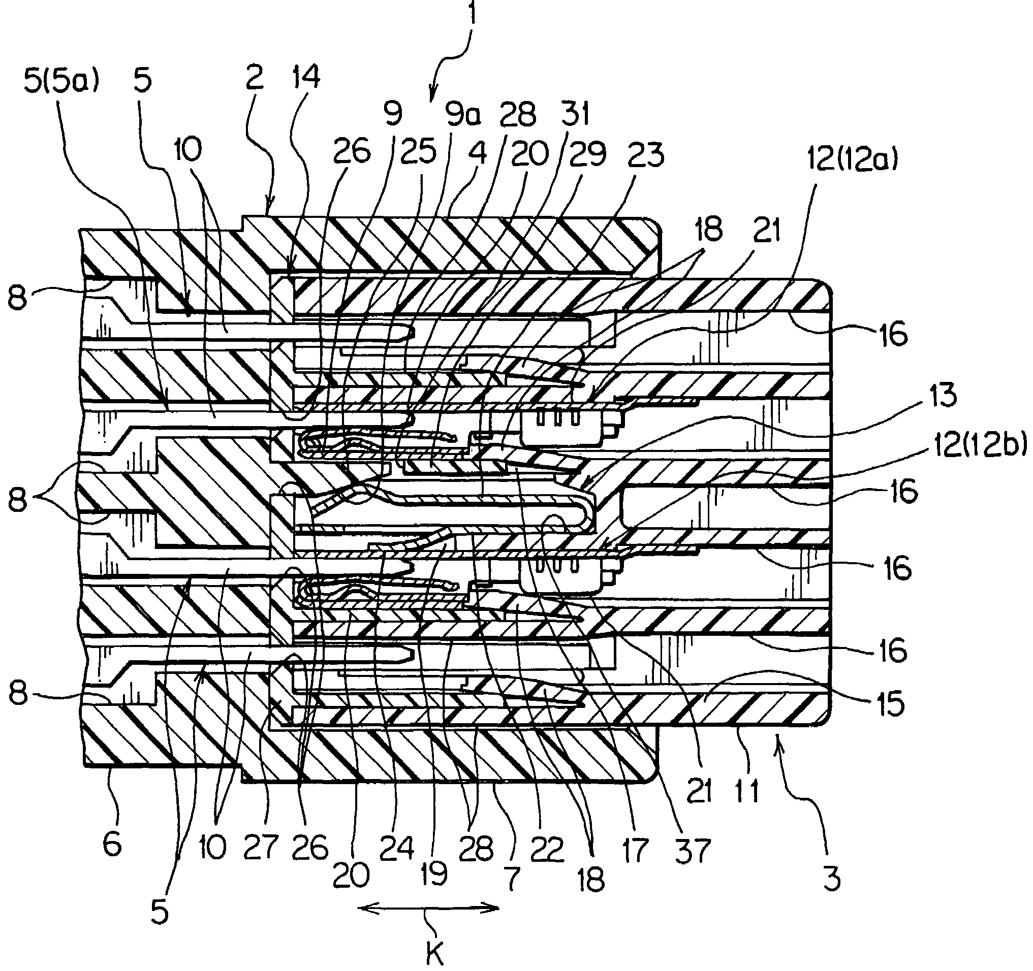
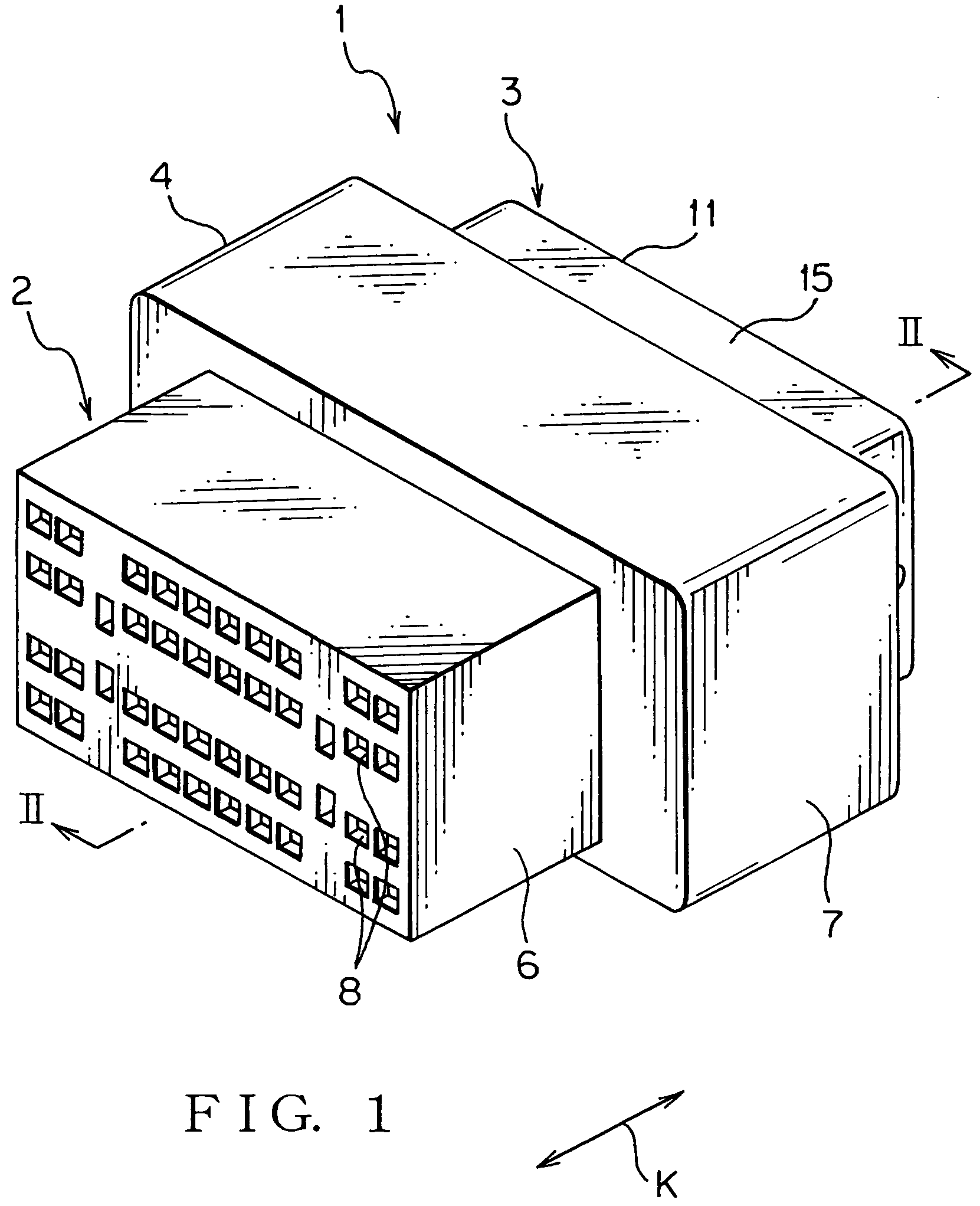
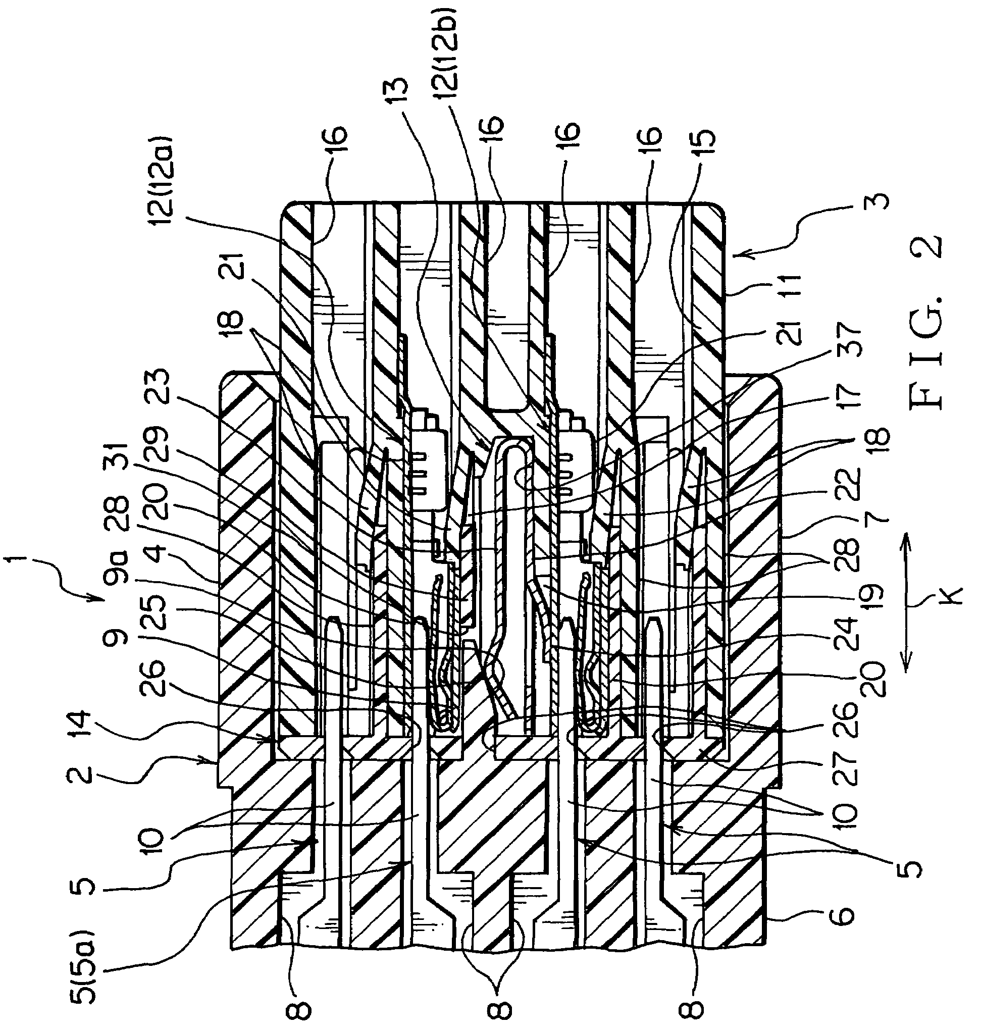
[0053]A connector unit 1 composes a wiring harness to be mounted on a motor vehicle and so on, and includes a mating connector 2 and a connector 3 as shown in FIGS. 1-4.

[0054]The mating connector 2 includes a mating connector housing 4 and male terminal fittings (hereinafter, male terminals; shown in FIGS. 2 and 4) 5 as mating terminal fittings. The mating connector housing 4 is made of electrically insulating synthetic resin and includes a box-shaped body part 6 and a tube-shaped drum part 7.

[0055]As shown in FIGS. 2 and 4, the body part 6 includes a plurality of terminal-receiving chambers 8, a releasing piece 9 as the releasing part, and a locking part (not shown in the figure). The terminal-receiving chamber 8 is a straight space formed in the body part 6. The terminal-receiving chambers 8 are arranged in parallel to one another.

[0056]In an example...


PUM


Abstract

The electric connector includes: at least two terminal fittings; a connector housing including terminal-receiving chambers each receiving the terminal fitting and having a locking piece for locking the terminal fitting; and a short circuit terminal for electrically connecting the two terminal fittings to each other, wherein when the connector is coupled with a mating connector, electrical connection between the two terminal fittings attained by the short circuit terminal is removed, wherein when the terminal fitting is inserted into the terminal-receiving chamber, the locking piece is once resiliently deformed and thereafter locks the terminal fitting, wherein the connector housing is provided with a bending space in which the locking piece is positioned when the locking piece is resiliently deformed, wherein the short circuit terminal includes a resilient contacting piece which passes through the bending space and comes in resilient contact with one terminal fitting of the two terminal fittings.

Description

BACKGROUND OF THE INVENTION[0001](1) Field of the Invention[0002]The present invention relates to an electric connector used for connection of electric wires and to an electric connector unit including the connector.[0003](2) Description of the Related Art[0004]Various electronic instruments are mounted on a motor vehicle as a mobile unit. The motor vehicle includes a wiring harness for transmitting electric power and control signals to the electronic instruments. The wiring harness includes a plurality of electric wires and connectors. The electric wire is a so-called coated wire which includes an electrically conductive core wire and an electrically insulating coating that coats the core wire.[0005]A connector (i.e. electric connector) to be connected to an air bag as the electronic instrument includes an electrically insulating connector housing, a terminal fitting received in the connector housing and connected to a gas generator of the air bag, another terminal fitting received...

Claims


Application Information

Patent Timeline
Patent Type & Authority Patents(United States)
IPC IPC(8): H01R29/00
CPCH01R13/7032
Inventor OHTAKA, KAZUTOTAKAHASHI, TOSHIHARU
Owner YAZAKI CORP
Why Eureka
Try Eureka