Magnet Structure For An Isochronous Superconducting Compact Cyclotron

Active Publication Date: 2014-12-18
ION BEAM APPL
View PDF5 Cites 30 Cited by
  • Summary
  • Abstract
  • Description
  • Claims
  • Application Information

AI Technical Summary

Benefits of technology

[0032]The present invention also relates to an isochronous cyclotron comprising a magnetic structure according to the invention. The cyclotron is preferably configured for producing a beam having an energy adapted for use in particle therapy. Advantageo

Problems solved by technology

If the flutter amplitude is too low, no stable beam can be generated.
However, for isochronous cyclotrons there is a fundamental limitation due to the fact that when further increasing the magnetic field strength, e.g. above 4 T, the relative contribution to the total magnetic field strength originating from the iron poles of the accelerator becomes small.
Indeed, the maximum contribution of the iron poles at satur

Method used


Image

  • Magnet Structure For An Isochronous Superconducting Compact Cyclotron
  • Magnet Structure For An Isochronous Superconducting Compact Cyclotron
  • Magnet Structure For An Isochronous Superconducting Compact Cyclotron

Examples


first embodiment

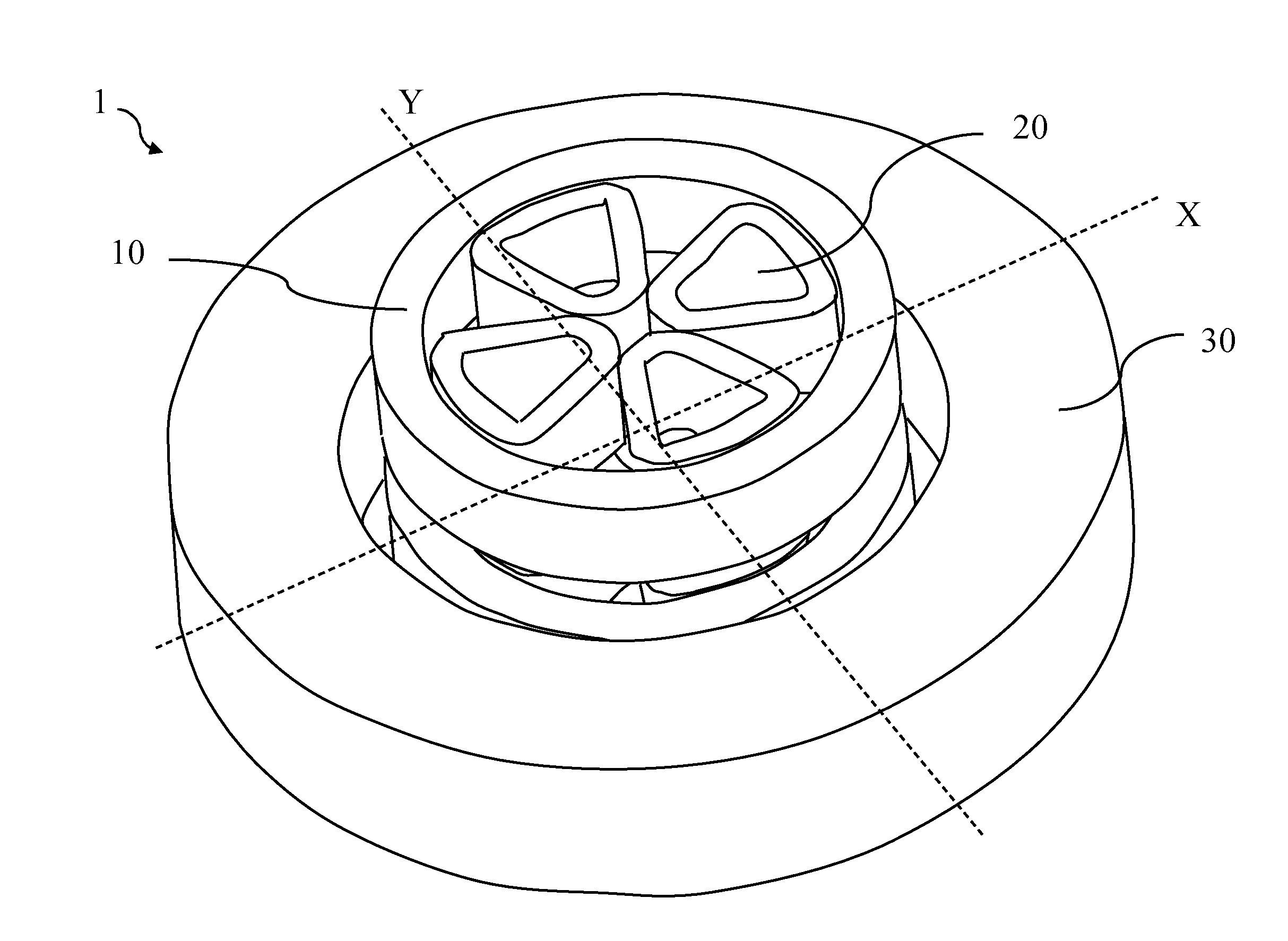
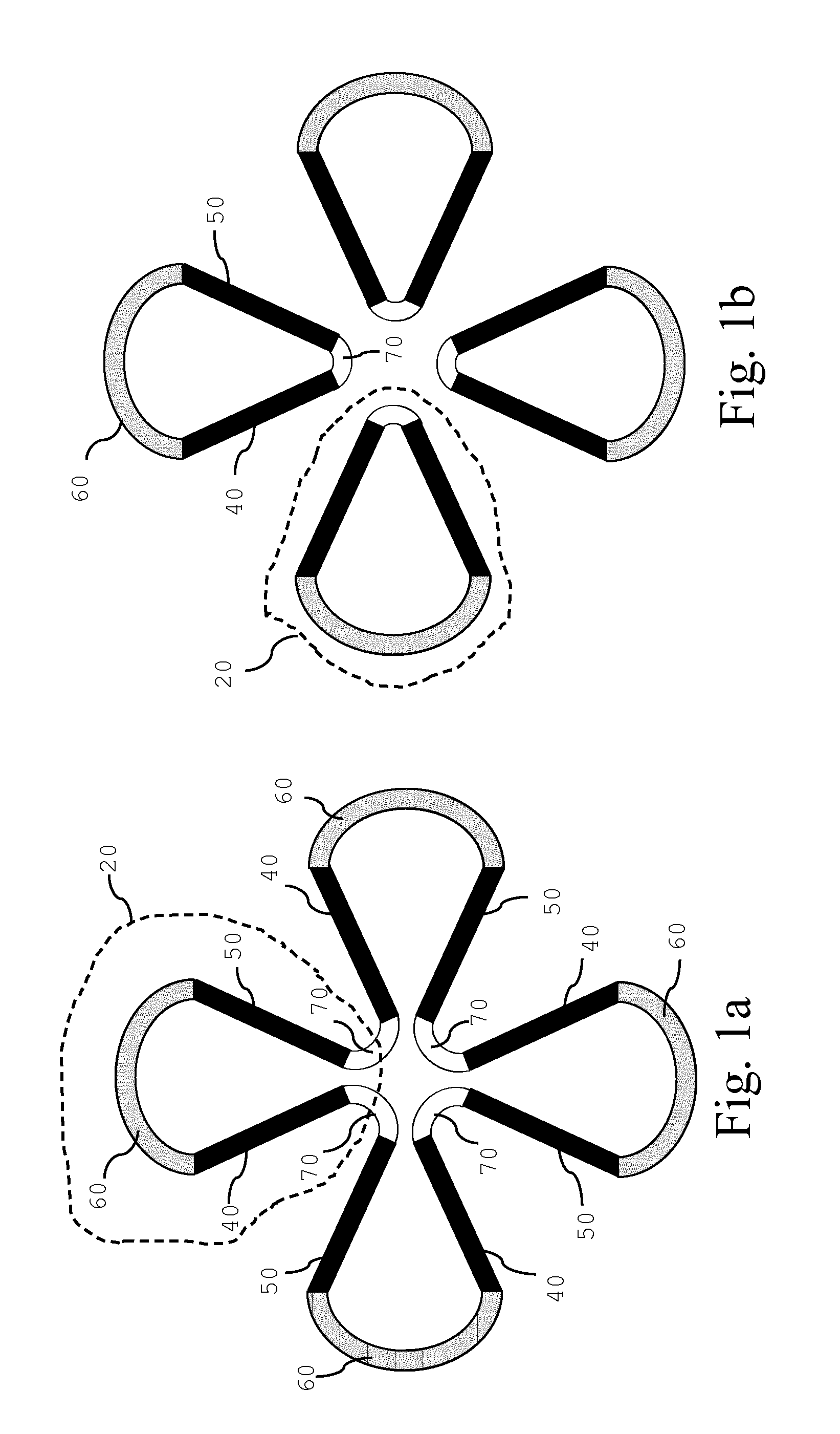
[0047]A magnet structure according to the invention comprises a superconducting coil assembly as represented on FIGS. 1a and 2a. It is characterized in that the superconducting coil assembly comprises one type of superconducting coils, namely a plurality of superconducting sector coil elements. The magnet structure represented on FIGS. 1a and 2a comprises a plurality of and preferably four sector coil elements 20 each comprising an outbound leg 40, an inbound leg 50, and an external return leg 60 for leading a current from the outbound leg 40 back to the inbound leg 50. In addition, an internal return leg 70 is provided for leading a current from one inbound leg 50 to an outbound leg 40 of an adjacent sector coil element 20, thereby forming a single clover-leaf shaped closed coil. As is well known, these coils may be formed from a plurality of individual leads wound along parallel paths.

[0048]In a preferred embodiment, the magnetic structure comprises two series of four sector coil ...

second embodiment

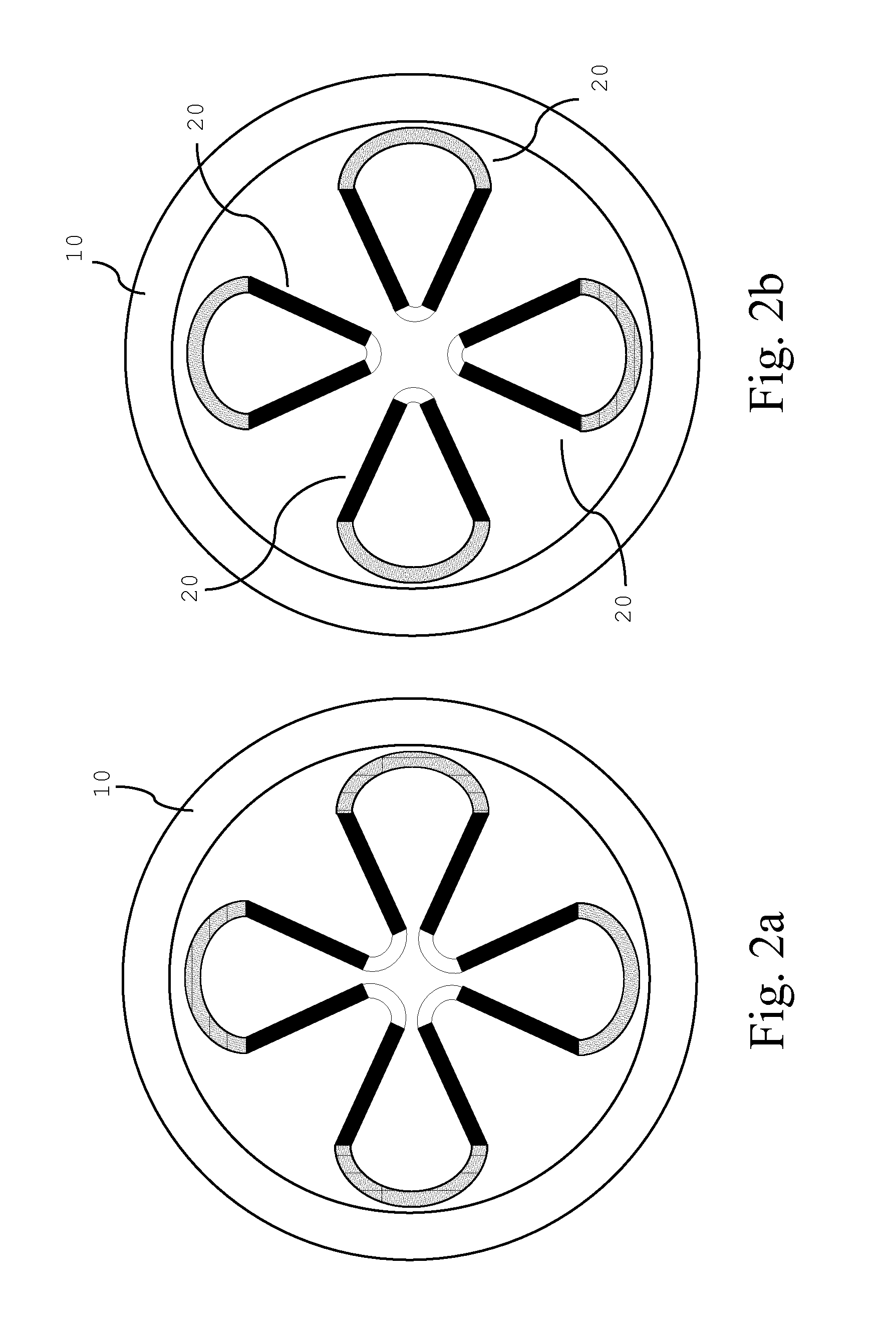
[0051]The magnet structure according to the invention represented on FIGS. 2, 3 and 4 is characterized in that the superconducting coil assembly comprises two types of superconducting coils. A first type of coils is a set of two superconducting annular coils 10 that are positioned around the circular acceleration region of the accelerator. The two coils 10 are spaced apart and located in a symmetric way on each side of the median plane. The acceleration region is located in the space between the two coils.

[0052]A second type of coils used are the superconducting sector coil elements 20 described above in relation to FIG. 1a or 1b. A series of superconducting sector coil elements 20 are installed on top and below the circular acceleration region and are located within the inner diameter of the coils 10. Three or more sector coil elements 20 can be installed in a symmetric way along each side of the median plane X,Y.

[0053]FIGS. 2a and 2b are top views corresponding to FIGS. 1a and 1b,...

third embodiment

[0065]The superconducting coil assembly of a magnetic structure according to the invention is shown in FIGS. 7a and 7b (top views). When compared to the embodiments of FIG. 1a and FIG. 1b, in these alternative embodiments, the superconducting coil assembly has in addition to the sector coil elements 20 also central coils 80. Those central coils 80 are located centrally in the acceleration region as shown in FIG. 7a and FIG. 7b. One central coil 80 is installed below and a second central coil 80 is installed above the acceleration region. These central coils 80 can be operated independently from the sector coil elements 20. In this way, the magnetic field in the centre of the accelerator can be adjusted. These central coils 80 can for example be used to reduce the magnetic field in the centre of the accelerator when a sector coil element configuration of FIG. 1a is adopted or they can be used to increase the magnetic field in the centre of the accelerator when a sector coil element c...


PUM


Abstract

The invention relates to a magnet structure for a superconducting isochronous cyclotron for use in particle therapy. The cyclotron according to the invention is using two sets of three or more superconducting sector coil elements for generating an azimuthally varying magnetic field across the acceleration region. In this way, high-field (e.g. above 4 T) isochronous cyclotrons are provided which do not suffer the problem of a low flutter amplitude.

Description

FIELD OF THE INVENTION[0001]The field of invention relates to a magnet structure for an isochronous compact cyclotron for accelerating charged particles in an acceleration region. The magnetic structure generates a magnetic field across an acceleration region and this magnetic field is perpendicular to a median plane of the acceleration region. A magnetic structure comprises[0002]a superconducting coil assembly,[0003]a ferro-magnetic assembly for guiding a magnetic flux,[0004]and a cavity forming said acceleration region.[0005]More particularly, the field of invention relates to a compact isochronous superconducting cyclotron for use in particle therapy. For example, for proton therapy, energies up to 250 MeV are preferably required.DESCRIPTION OF PRIOR ART[0006]Compact isochronous superconducting cyclotrons with a magnetic structure that combines a superconducting coil assembly with a ferro-magnetic assembly are known. Such a ferro-magnetic assembly, generally made out of iron, can...

Claims


Application Information

Patent Timeline
IPC IPC(8): H01F6/06A61N5/10H05H7/04
CPCH01F6/06A61N5/1077H05H7/04H05H13/005H05H2007/043
Inventor JONGEN, YVES
Owner ION BEAM APPL
Why Eureka
Try Eureka