Magnet structure for an isochronous superconducting compact cyclotron
a superconducting compact cyclotron and magnet structure technology, applied in superconducting magnets/coils, x-ray/gamma-ray/particle-irradiation therapy, radiation therapy, etc., can solve the problem of inability to generate stable beams, small relative contribution to the total magnetic field strength originating from the iron poles of the accelerator, and inability to achieve stable beams
- Summary
- Abstract
- Description
- Claims
- Application Information
AI Technical Summary
Benefits of technology
Problems solved by technology
Method used
Image
Examples
first embodiment
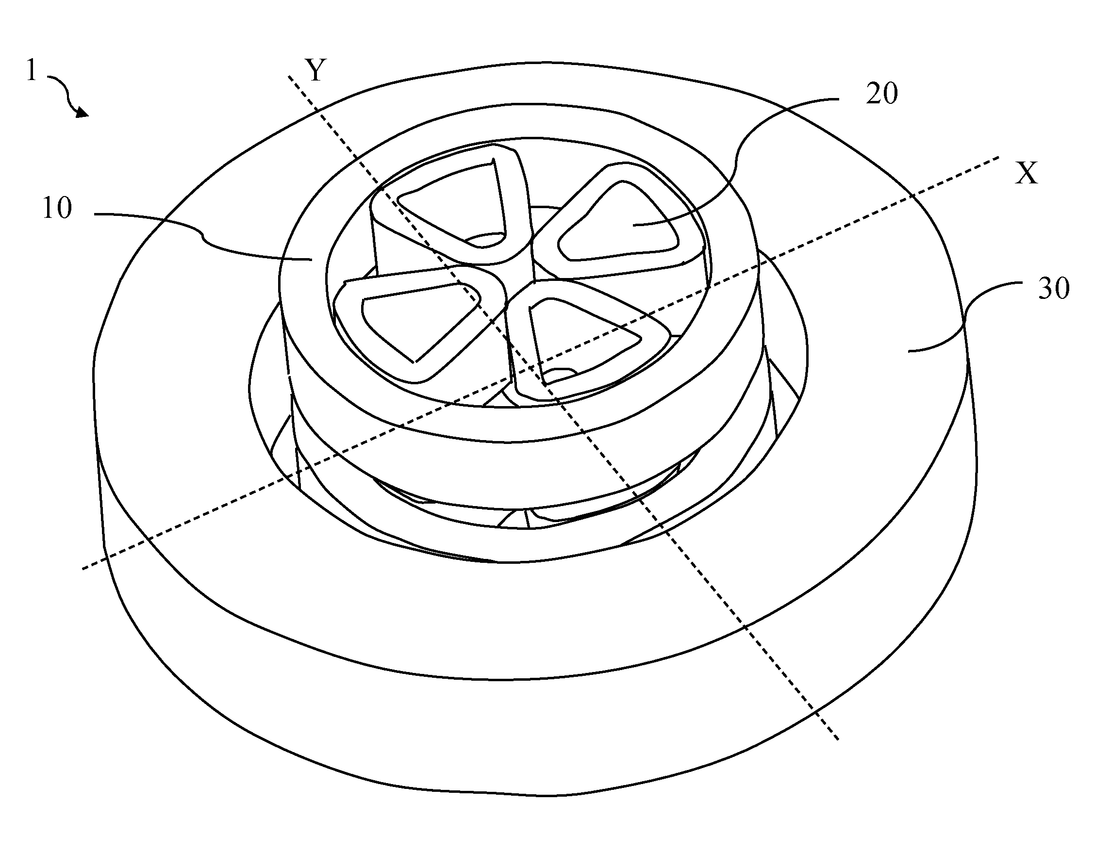
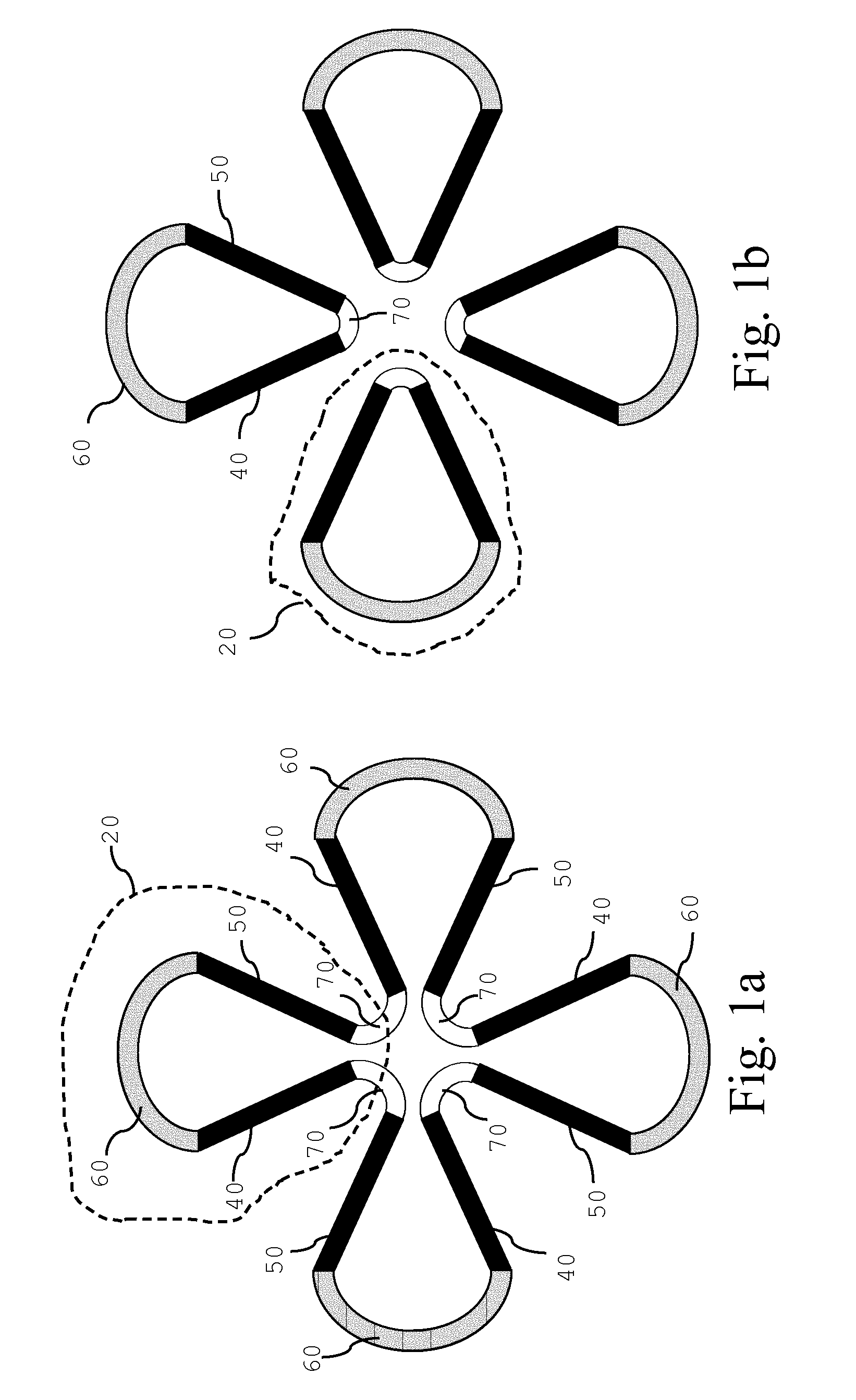
[0048]A magnet structure according to the invention comprises a superconducting coil assembly as represented on FIGS. 1a and 2a. It is characterized in that the superconducting coil assembly comprises one type of superconducting coils, namely a plurality of superconducting sector coil elements. The magnet structure represented on FIGS. 1a and 2a comprises a plurality of and preferably four sector coil elements 20 each comprising an outbound leg 40, an inbound leg 50, and an external return leg 60 for leading a current from the outbound leg 40 back to the inbound leg 50. In addition, an internal return leg 70 is provided for leading a current from one inbound leg 50 to an outbound leg 40 of an adjacent sector coil element 20, thereby forming a single clover-leaf shaped closed coil. As is well known, these coils may be formed from a plurality of individual leads wound along parallel paths.
[0049]In a preferred embodiment, the magnetic structure comprises two series of four sector coil ...
second embodiment
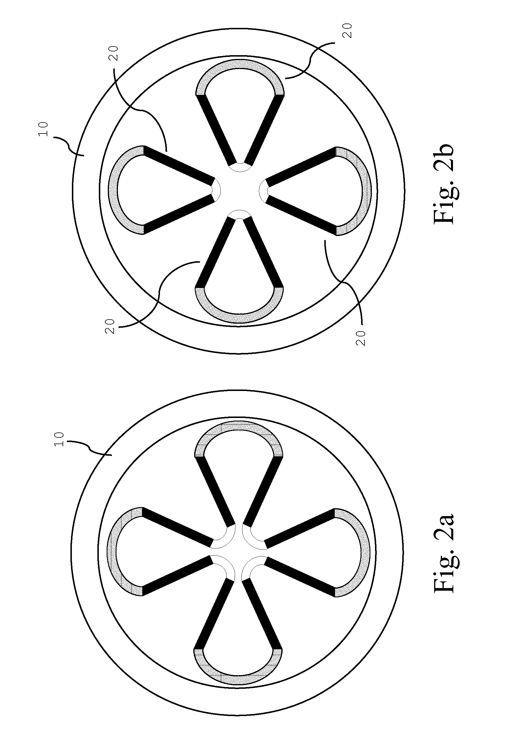
[0052]The magnet structure according to the invention represented on FIGS. 2, 3 and 4 is characterized in that the superconducting coil assembly comprises two types of superconducting coils. A first type of coils is a set of two superconducting annular coils 10 that are positioned around the circular acceleration region of the accelerator. The two coils 10 are spaced apart and located in a symmetric way on each side of the median plane. The acceleration region is located in the space between the two coils.
[0053]A second type of coils used are the superconducting sector coil elements 20 described above in relation to FIG. 1a or 1b. A series of superconducting sector coil elements 20 are installed on top and below the circular acceleration region and are located within the inner diameter of the coils 10. Three or more sector coil elements 20 can be installed in a symmetric way along each side of the median plane X,Y.
[0054]FIGS. 2a and 2b are top views corresponding to FIGS. 1a and 1b,...
third embodiment
[0066]The superconducting coil assembly of a magnetic structure according to the invention is shown in FIGS. 7a and 7b (top views). When compared to the embodiments of FIG. 1a and FIG. 1b, in these alternative embodiments, the superconducting coil assembly has in addition to the sector coil elements 20 also central coils 80. Those central coils 80 are located centrally in the acceleration region as shown in FIG. 7a and FIG. 7b. One central coil 80 is installed below and a second central coil 80 is installed above the acceleration region. These central coils 80 can be operated independently from the sector coil elements 20. In this way, the magnetic field in the centre of the accelerator can be adjusted. These central coils 80 can for example be used to reduce the magnetic field in the centre of the accelerator when a sector coil element configuration of FIG. 1a is adopted or they can be used to increase the magnetic field in the centre of the accelerator when a sector coil element c...
PUM
| Property | Measurement | Unit |
|---|---|---|
| magnetic field | aaaaa | aaaaa |
| magnetic field | aaaaa | aaaaa |
| magnetic field | aaaaa | aaaaa |
Abstract
Description
Claims
Application Information
 - R&D
- Intellectual Property
- Life Sciences
- Materials
- Tech Scout
- Unparalleled Data Quality
- Higher Quality Content
- 60% Fewer Hallucinations
Browse by: Latest US Patents, China's latest patents, Technical Efficacy Thesaurus, Application Domain, Technology Topic, Popular Technical Reports.
© 2025 PatSnap. All rights reserved.Legal|Privacy policy|Modern Slavery Act Transparency Statement|Sitemap|About US| Contact US: help@patsnap.com


