Multi-reflector LED light source with cylindrical heat sink

a technology of led light source and heat sink, which is applied in the direction of semiconductor devices for light sources, light and heating apparatus, transportation and packaging, etc., can solve the problems of enlarge the emitting area and complicate thermal management, and achieve the effect of safe handling, high optical efficiency of the system, and simple structur

Inactive Publication Date: 2011-03-15
LIGHT PRESCRIPTIONS INNOVATORS
View PDF19 Cites 36 Cited by
  • Summary
  • Abstract
  • Description
  • Claims
  • Application Information

AI Technical Summary

Benefits of technology

Each LED, or group of LEDs, has its own reflector, which forms an output beam running along the cylinder axis. A plurality of such LEDs, preferably four or more, and their reflectors are nested outside and / or inside the cylinder, with the light coming out one end of the reflector. The electrical power cabling and mechanical supports may come out the other end of the reflector. The combined light output of the four or more reflectors forms a typical PAR-type flood pattern. The advantage of this approach is multi-fold. The optical efficiency of the system is very high as the only losses come from absorption losses of light striking the reflectors. As such the intercept efficiency is typically at 90% (amount of light from the LED that gets to the target, with optical efficiency=reflectivity*intercept efficiency). In addition, the design may be made extremely compact allowing the system to operate inside a conventional 6 inch (15 cm) diameter ceiling can of conventional downlights.
Furthermore, the architecture aids in the creation of thermal cooling via convection loops even inside an insulated can. Using state-of-the-art white LEDs, the system can safely handle 15 watts of electrical power input to the LEDs (of which about ¾ is converted into heat) even with the system installed in an insulated can, as long as the room temperature is 35° C. or less. For example, using five CREE Corporation (of North Carolina) model MC-E white LEDs, flux levels of well over 1400 lumens (cool white) can be projected onto the floor. Using warmer color LEDs from the same manufacturer and others, the system can output approximately one thousand lumens with a color temperature under the 3000° K of incandescent light bulbs. This can be achieved with a sizable temperature safety margin for the system components. Thus this new approach makes it possible to produce solid state replacement lamps for the most popular PAR 20 and PAR 30 lamps, and even some PAR 38 lamps.

Problems solved by technology

That approach, however, enlarges the emitting area and complicates thermal management.

Method used


Image

  • Multi-reflector LED light source with cylindrical heat sink
  • Multi-reflector LED light source with cylindrical heat sink
  • Multi-reflector LED light source with cylindrical heat sink

Examples


Embodiment Construction

A better understanding of the features and advantages of the present invention will be obtained by reference to the following detailed description of the invention and accompanying drawings, which set forth illustrative embodiments in which various principles of the invention are utilized.

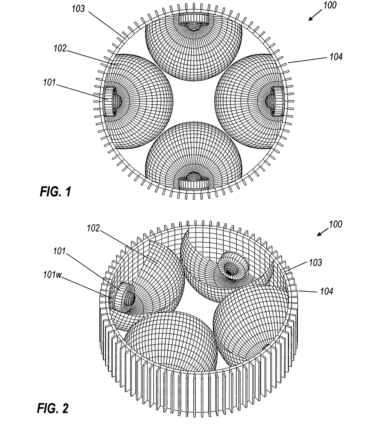
Referring to the drawings, and initially to FIGS. 1 through 5, FIG. 1 shows a plan view of an embodiment of a light source, indicated generally by the reference number 100, comprising LED packages 101, ellipsoidal reflectors 102, mounting cylinder 103, and convective fins 104. The ellipsoidal reflectors 102 are mounted on the inside of the cylinder 103, with each LED package 101 mounted centrally within a respective reflector 102. The fins 104 extend axially along, and project radially from, the outside of the cylinder 103. When the light source 100 is mounted in a ceiling can, the view shown in FIG. 1 is the view of the light source 100 as seen looking up from the floor.

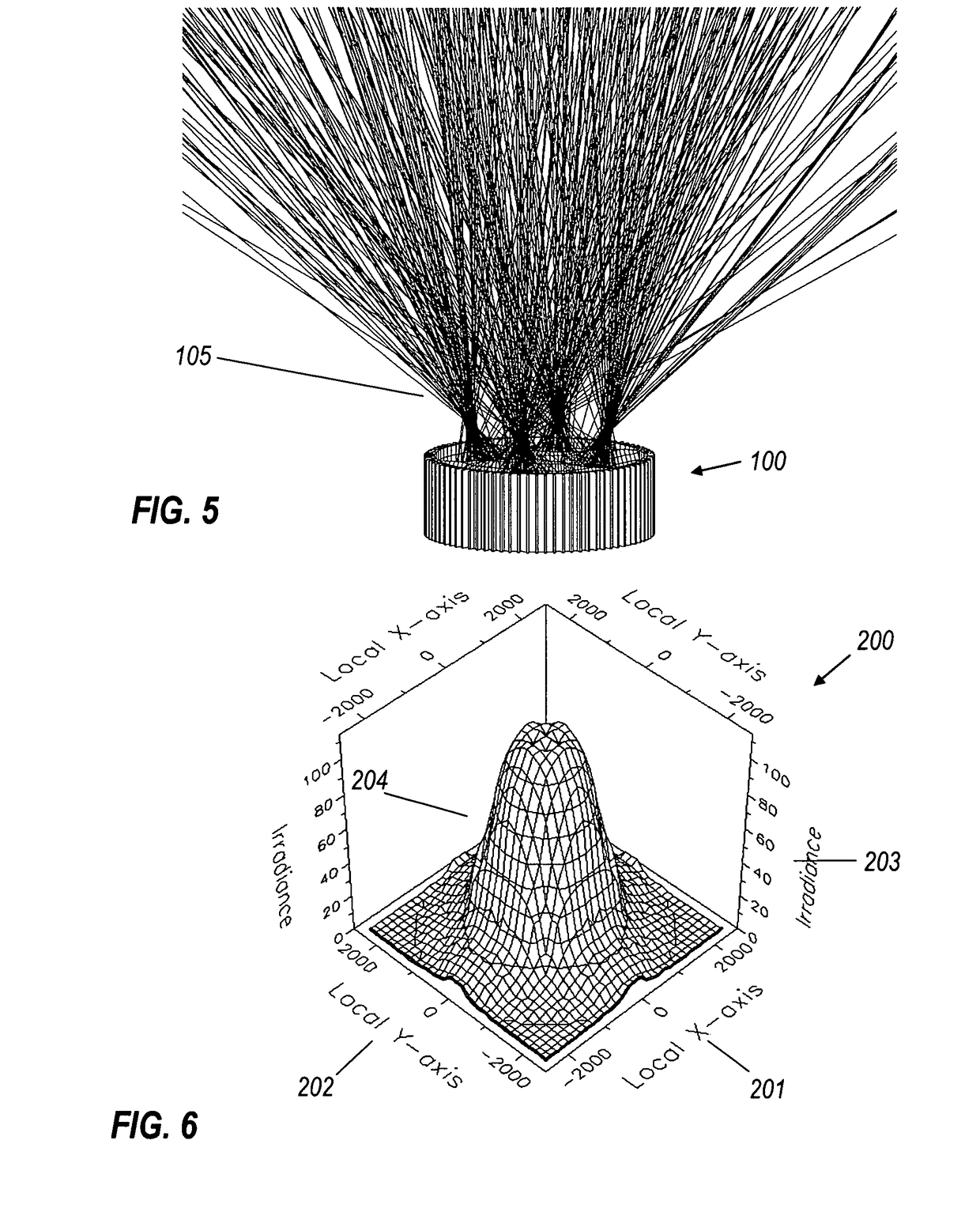
The downward intensity of t...


PUM


Abstract

A cylindrical light source comprises multiple LEDs mounted on either the exterior or interior surface of the cylinder, with heat-sink fins respectively on its interior or exterior. The LEDs emit radially, but their emission is redirected along the cylinder axis by individual ellipsoidal reflectors.

Description

BACKGROUND OF THE INVENTIONIn the ongoing endeavor to use multiple light emitting diodes (LEDs) in commercial lighting fixtures, there are two primary aspects, optical and thermal, that require careful consideration. Several US patents disclose reflective types of LED combiners. In U.S. Pat. Nos. 7,246,919 B2; 6,846,100 B2; 6,598,996 B1; and 6,364,506 an array of LEDs is mounted on a planar base, attached to an Edison screw connector. That approach, however, enlarges the emitting area and complicates thermal management. U.S. Pat. Nos. 7,249,877 and 6,682,211 B2 put an LED array at a location corresponding to the filament location of a corresponding incandescent bulb, but cooling is adequate only for low-power LEDs. What is needed is a fresh approach to multiple-LED employment, offering both superior cooling and compact beam-forming optics.SUMMARY OF THE INVENTIONOne aspect of the present invention is a complete light source, comprising multiple LEDs, their optics, drive electronics,...

Claims


Application Information

Patent Timeline
Patent Type & Authority Patents(United States)
IPC IPC(8): F21V7/00F21V29/505
CPCF21K9/00F21V7/0016F21V29/777F21V29/004F21Y2101/02F21K9/68F21Y2115/10
Inventor AGUROK, ILYAFALICOFF, WAQIDIPARKYN, WILLIAM A.DROSS, OLIVER
Owner LIGHT PRESCRIPTIONS INNOVATORS
Why Eureka
Try Eureka