

Air compressor
- Summary
- Abstract
- Description
- Claims
- Application Information
AI Technical Summary
Benefits of technology
Problems solved by technology
Method used
Image

Examples
first embodiment
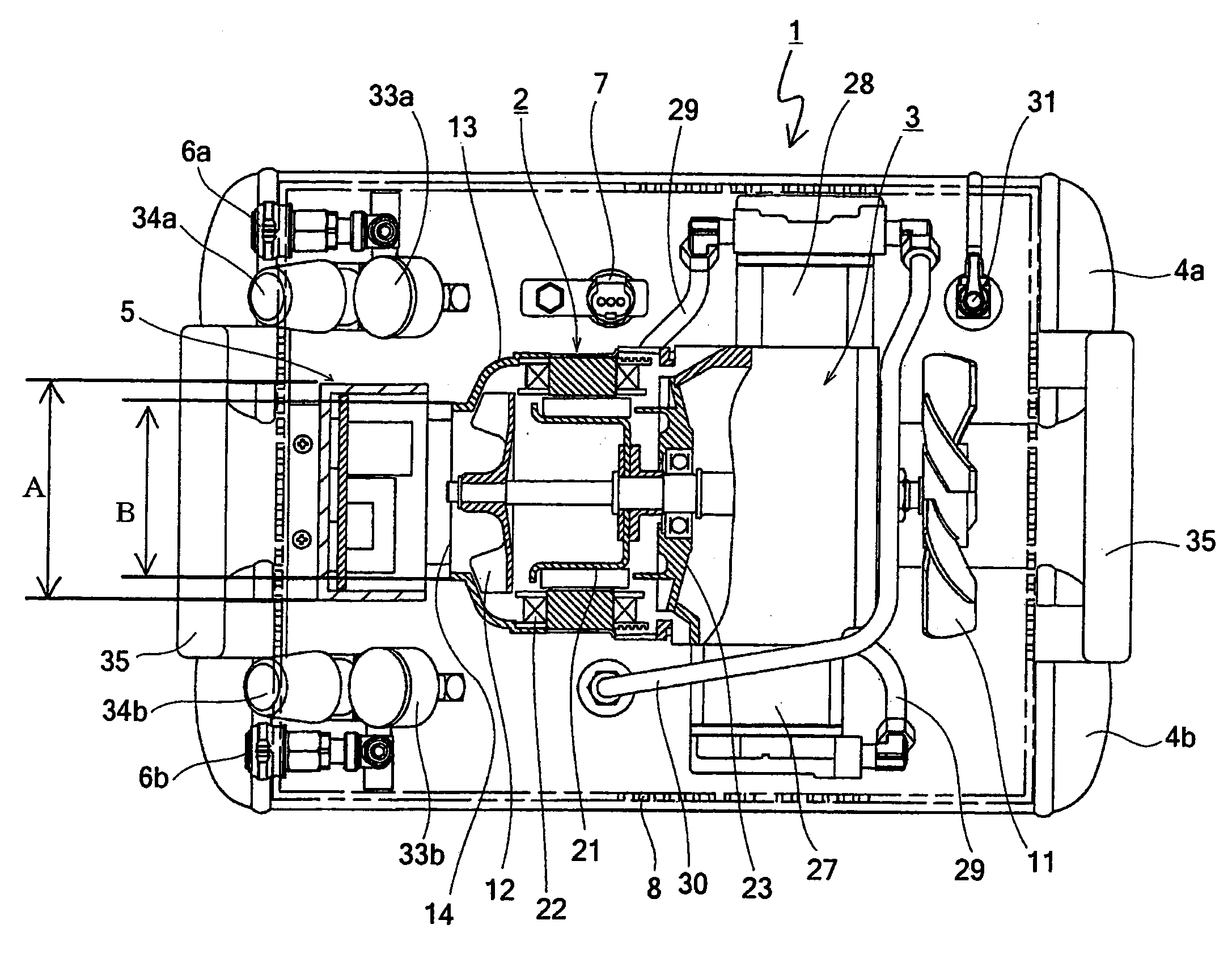
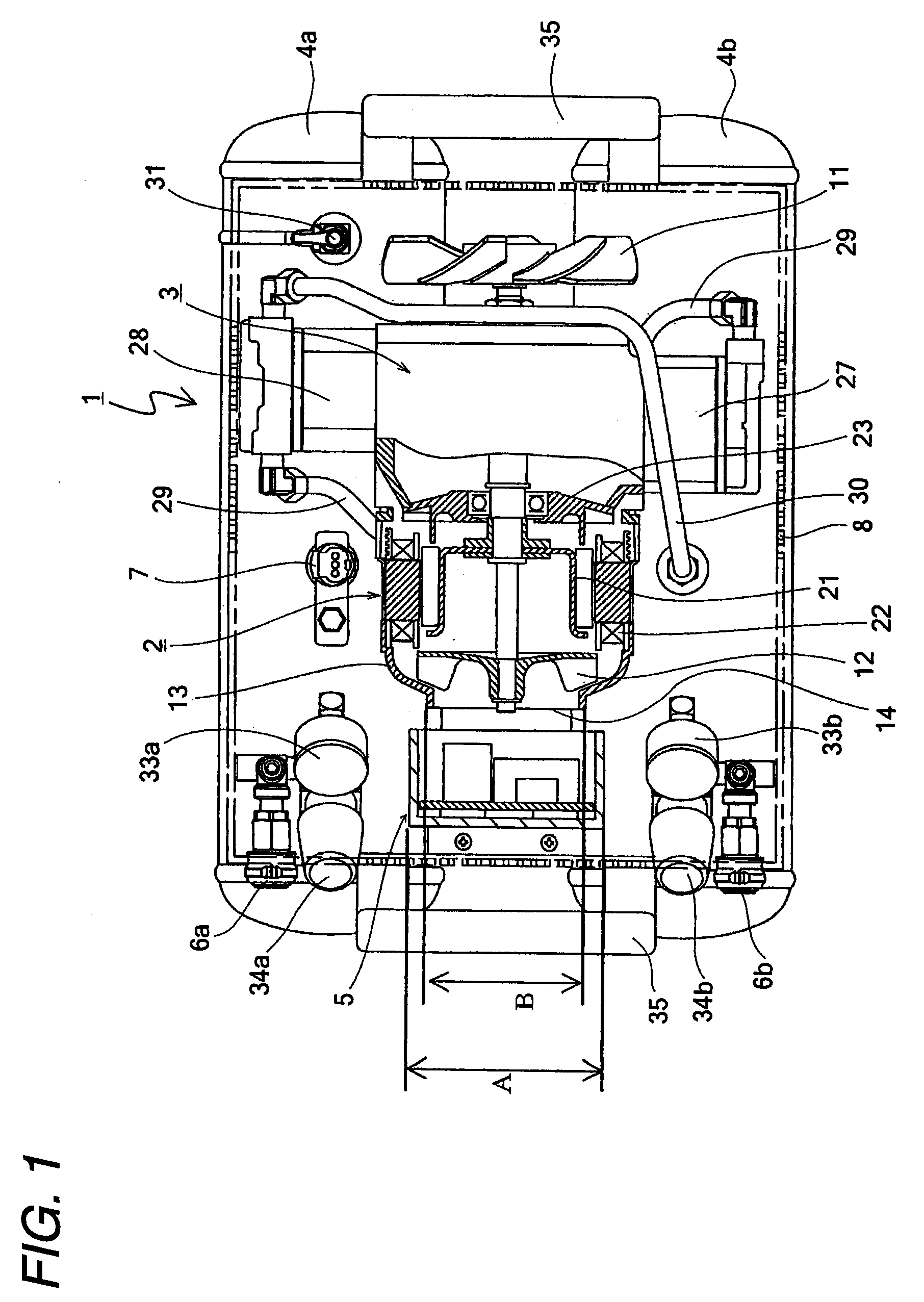
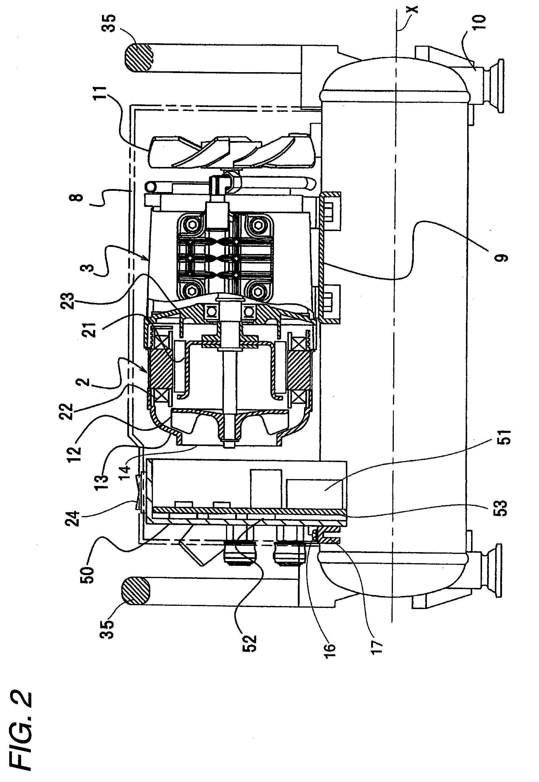
[0071]FIG. 1 is an upper view for showing an entire structure of an air compressor mode of the present invention, and is a partially sectional view thereof. FIG. 2 is a side view for indicating the air compressor shown in FIG. 1, and is a partially sectional view thereof. FIG. 3 is a front view for explaining air flows of the air compressor represented in FIG. 1.
[0072]As represented in FIG. 1 to FIG. 3, an air compressor 1 according to the first embodiment mode of the present invention contains: one pair of air tanks 4a and 4b for storing thereinto compressed air; a compressing unit 3 for producing compressed air so as to supply the produced compressed air to the air tank 4b; a motor unit 2 for driving a motor; and a control circuit unit 5 for controlling initiating and stopping operations (ON / OFF operations) of the motor. In the drawings, portions indicated by a two-dot and chain line are sectional planes of a main body cover 8. The main body cover 8 covers at least upper portions...
third embodiment
[0087]Next, a description is made of a further embodiment mode according to the present invention with reference to FIG. 7. FIG. 7 is an upper view for showing an entire structure of an air compressor mode of the present invention, and indicates a partially sectional view thereof. In FIG. 7, at a portion of a circumference of a fan guide 132 having a semi-spherical shape, for example, at two right and left portions, air ejecting ports 133 are formed, so that a portion of air may be conducted into the interior portion of the motor, and the remaining air may be ejected via the air ejecting ports 133 to the external space. In the example of FIG. 7, the air ejecting ports 133 are provided only in the right and left portions of the motor; and in the upper and lower portions, no opening portion is provided around the fan guide 132. A portion of air flows sucked by the cooling fan 12 via the air ejecting ports 133 can be exhausted outside the fan guide 132 without passing through the spac...
fourth embodiment
[0094]Next, a description is made of an air compressor 1 mode of the present invention.
[0095]Firstly, a description is made of a structure of the air compressor 1 according to fourth embodiment mode. As shown in FIG. 8 and FIG. 9 (namely, FIG. 9 is sectional view of air compressor 1, taken along arrow line A-A of FIG. 8), the air compressor 1 is constructed by employing a motor unit 2, a compressing unit 3, an air tank 4 (4a and 4b), a pressure sensor 97, couplers 6, cooling fans 11 and 12, an operation panel 99, a frame 90, a control circuit unit 5, and a main body cover 8.
[0096]The motor unit 2 corresponds to a power source of the air compressor 1, and is fixed on a horizontal frame (not shown) at a center portion of the air compressor 1 so as to be mounted on this horizontal frame. The motor unit 2 is driven by the control circuit unit 5 in an inverter mode.
[0097]The air tank 4 is equipped with one pair of air tanks 4a and 4b which are formed in long body shapes so as to store t...
PUM
 Abstract
Description
Claims
Application Information