Compensating for printing non-uniformities using a one dimensional map

Active Publication Date: 2015-07-30
EASTMAN KODAK CO
View PDF1 Cites 1 Cited by
  • Summary
  • Abstract
  • Description
  • Claims
  • Application Information

AI Technical Summary

Benefits of technology

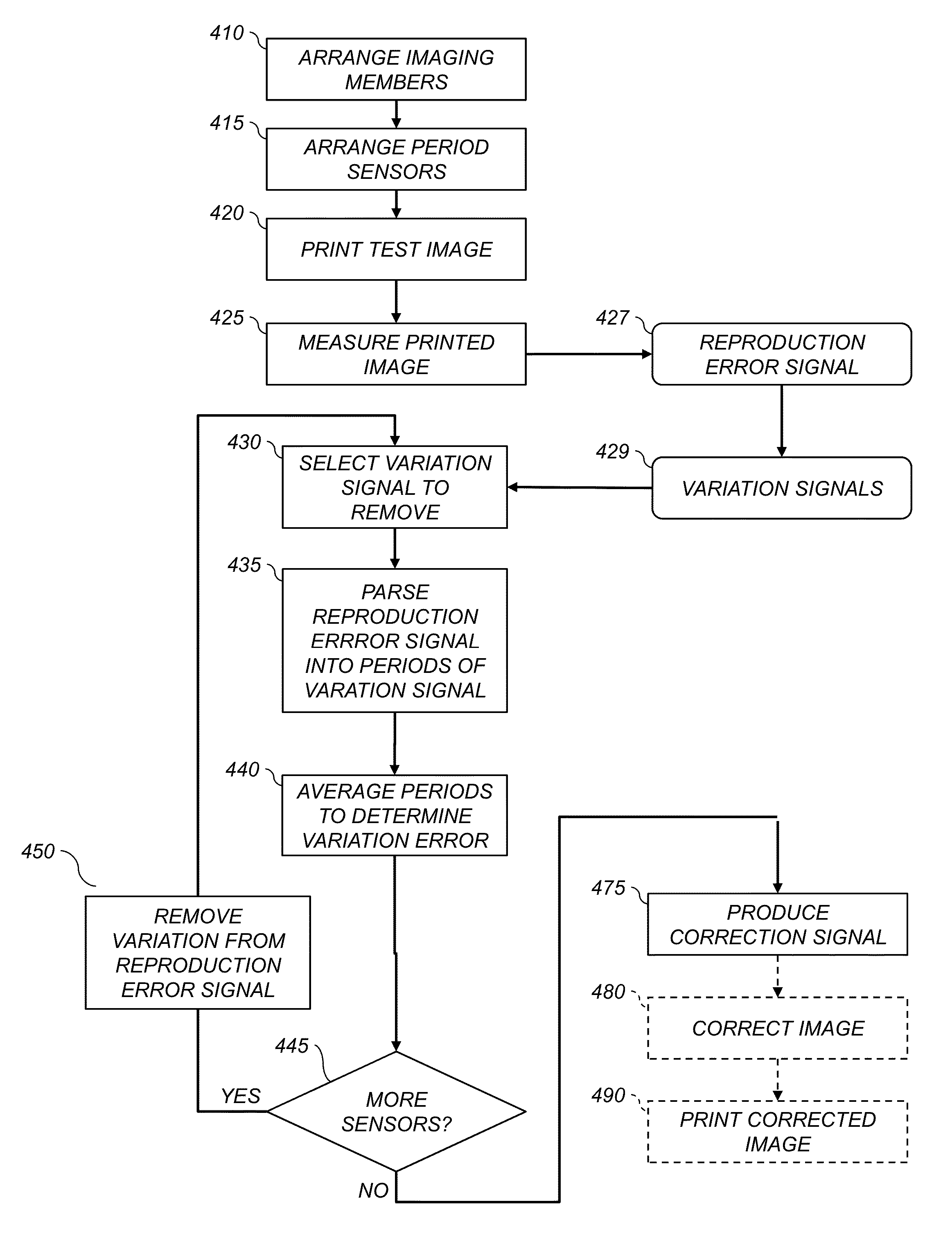
[0011]A method for compensating for imaging defects in an electro-photographic imaging system, the method comprising the steps of providing one or more imaging elements that rotates while printing; determining positions on the one or more imaging elements using a period sensor while printing an image of known target density; measuring the density image at one cross-track location; determining a one dimensional map of the in-track density for each of the one or more period sensors; wherein each of the imaging maps corresponds to positions on the one or more imaging elements; comparing the printed density at each of the positions of the imaging maps to the known target density for determining an error signal; determini

Problems solved by technology

Various components used in printing processes, such as belts and drums, can have mechanical or electrical characteristics that result in periodic objectionable non-uniformities in print images, such as streaks (extending in-track), bands (extending cross-track) and irregular two dimensional patterns.
Damped springs for mounting components can experience periodic vibrations, causing the spacing between the mounted comp

Method used


Image

  • Compensating for printing non-uniformities using a one dimensional map
  • Compensating for printing non-uniformities using a one dimensional map
  • Compensating for printing non-uniformities using a one dimensional map

Examples


Example

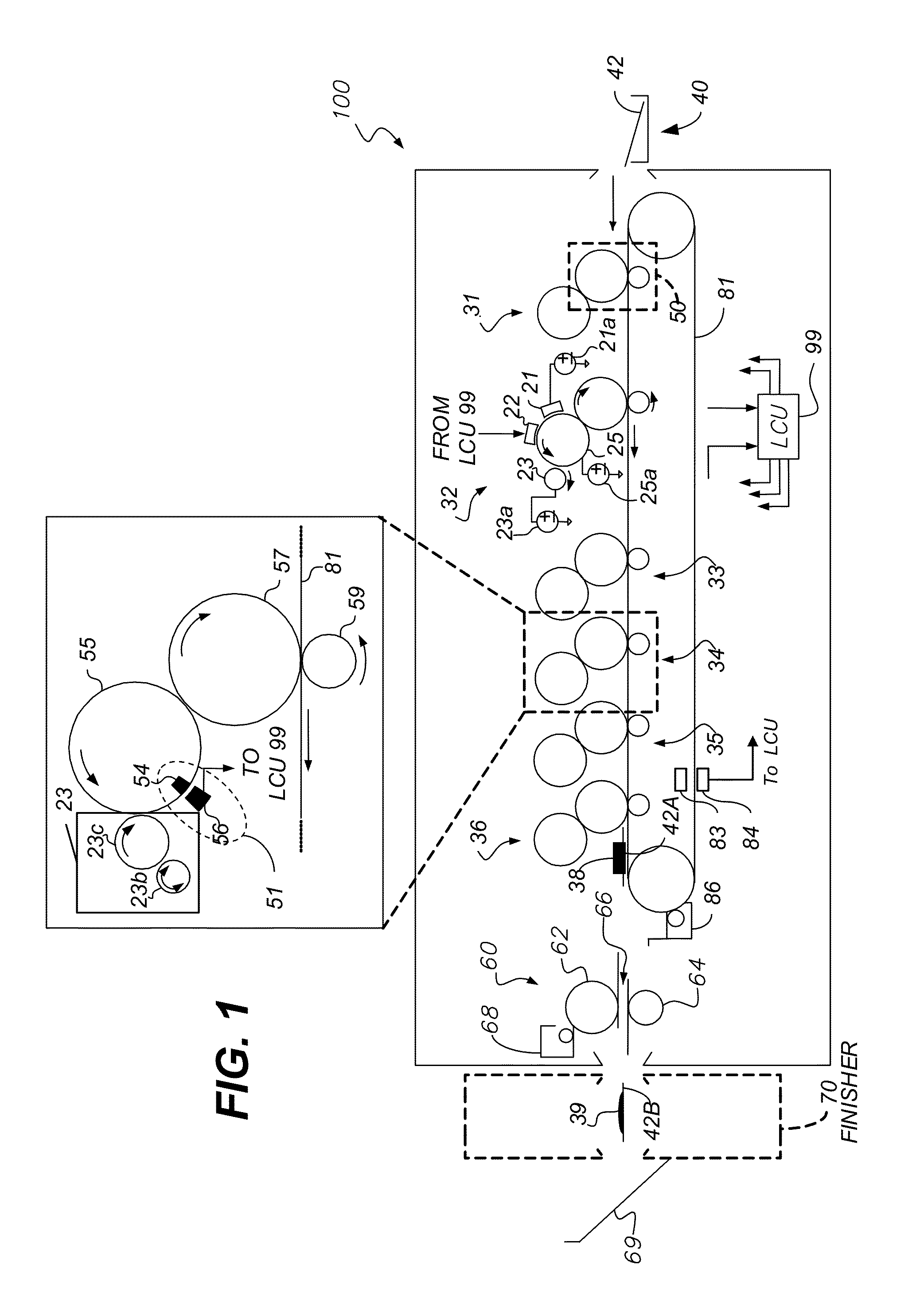
[0021]The attached drawings are for purposes of illustration and are not necessarily to scale.

DETAILED DESCRIPTION OF THE INVENTION

[0022]In the following description, some embodiments will be described in terms that would ordinarily be implemented as software programs. Those skilled in the art will readily recognize that the equivalent of such software can also be constructed in hardware. Because data-manipulation algorithms and systems are well known, the present description will be directed in particular to algorithms and systems forming part of, or cooperating more directly with, methods described herein. Other aspects of such algorithms and systems, and hardware or software for producing and otherwise processing the compensation data and image signals involved therewith, not specifically shown or described herein, are selected from such systems, algorithms, components, and elements known in the art. Given the system as described herein, software not specifically shown, suggested...


PUM


Abstract

Correction data is produced for density errors in prints produced using a printer. While printing a test image, the periods of rotation of one or more rotatable imaging members arranged along a receiver feed path in the printer are measured using a period sensor. The printed test image is measured in the cross-track direction and a one dimensional map of the period sensors is determined. A reproduction error signal representing deviation from aim density is determined. The variations from the data at measured periods in one or both directions are used to produce a correction signal.

Description

CROSS-REFERENCE TO RELATED APPLICATIONS[0001]This application has related subject matter to U.S. patent application Ser. No. 13 / 076,467, filed Mar. 31, 2011, titled “COMPENSATING FOR PERIODIC NONUNIFORMITY IN ELECTROPHOTOGRAPHIC PRINTER,” by Thomas A. Henderson et al., and U.S. patent application Ser. No. 13 / 331,075, filed Dec. 20, 2011, titled “PRODUCING CORRECTION DATA FOR PRINTER,” by Chung-Hui Kuo et al, U.S. patent application Ser. No. ______ filed concurrently herewith, titled COMPENSATING FOR PRINTING NON-UNIFORMITIES USING A TWO DIMENSIONAL MAP, by Michael T. Dobbertin et al., the disclosures of which are incorporated herein by reference.FIELD OF THE INVENTION[0002]This invention pertains to the field of printing and more particularly to compensating for non-uniformities in prints.BACKGROUND OF THE INVENTION[0003]Printers are useful for producing printed images of a wide range of types. Printers print on receivers (or “imaging substrates”), such as pieces or sheets of paper ...

Claims


Application Information

Patent Timeline
IPC IPC(8): G03G15/00
CPCG03G15/55G03G15/5054G03G15/5008G03G15/5033G03G15/5062
Inventor DOBBERTIN, MICHAEL THOMASALLEN, RICHARD GEORGE
Owner EASTMAN KODAK CO
Why Eureka
Try Eureka