This helps you quickly interpret patents by identifying the three key elements:
Problems solved by technology
Method used
Benefits of technology
Benefits of technology
[0023]One or more exemplary embodiments of the present invention provide a grazing incidence interferometer which can widen the measurement range while simplifying the measuring instrument.
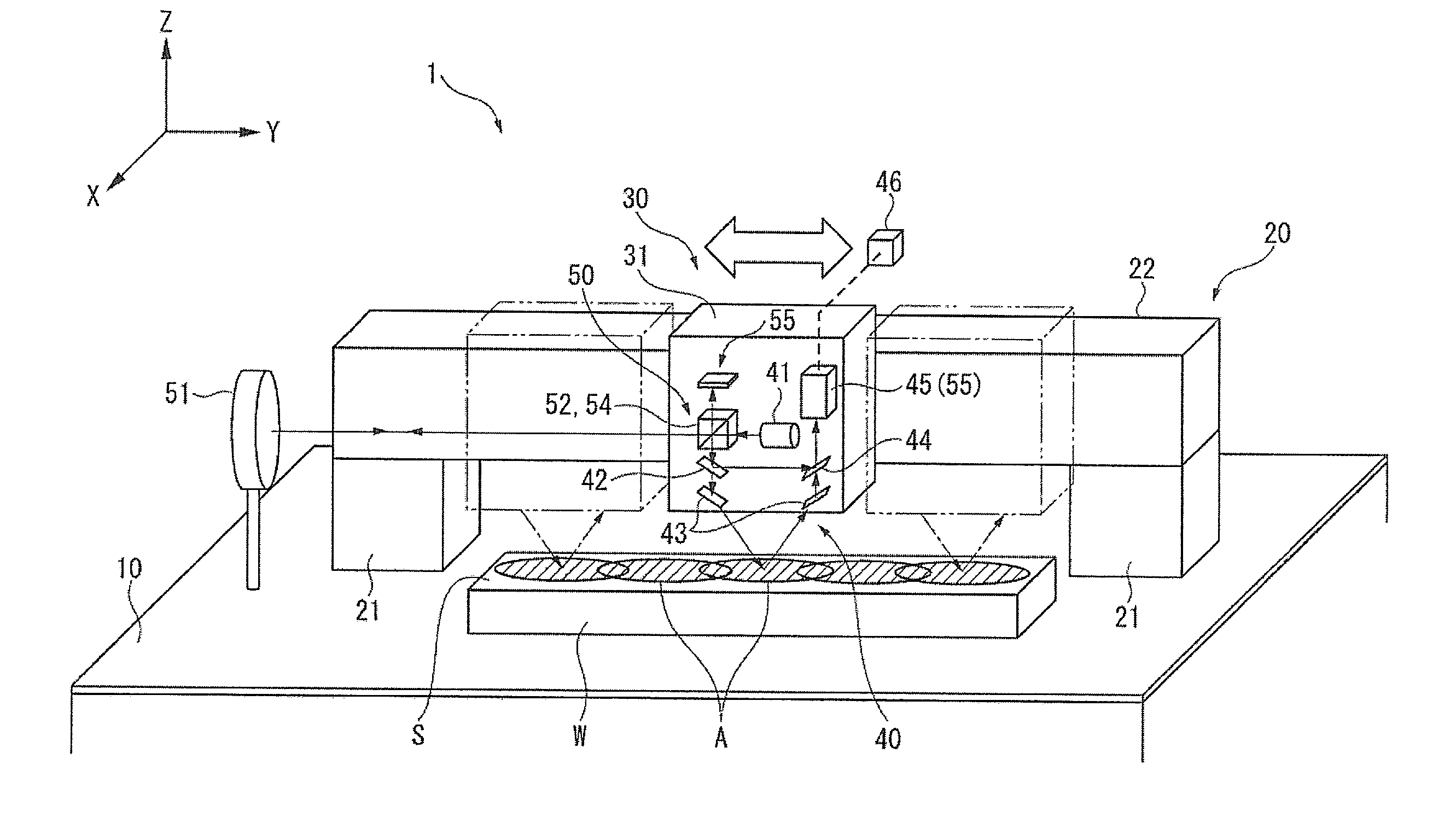
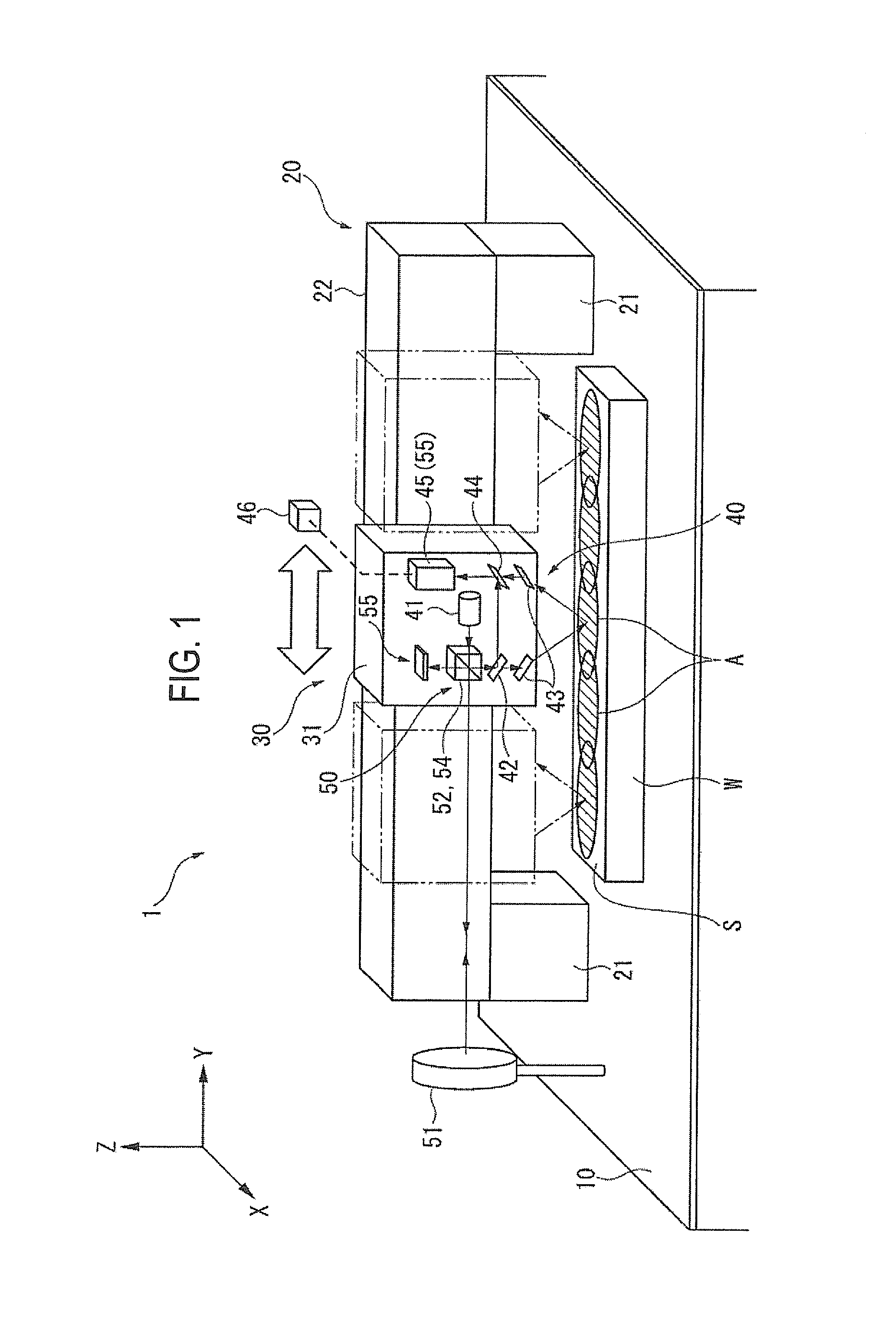
[0042]To perform a scanning measurement, information indicating a position of the interferometer main body with respect to the stage is acquired from a control system of the moving mechanism which moves the interferometer main body. Furthermore, a change in the posture (e.g., inclination) of the interferometer main body with respect to the stage is detected with high accuracy by measuring the state of auxiliary light reflected from the auxiliary reflector with an auxiliary optical system which includes the auxiliary light beam separator and the auxiliary photodetector which are provided in the interferometer main body. The above-mentioned position information of the interferometer main body is corrected using the thus-detected position change of the interferometer main body to obtain highly accurate position information. The accuracy of connections of measurement results of the plural sections is increased using such pieces of highly accurate position information, whereby a high-accuracy scanning measurement can be realized.
[0043]The light source of the measurement optical system can also be used by the auxiliary optical system for detecting a posture of the interferometer main body, and elements (the light beam divider to the photodetector) of the measurement optical system can also be used by the auxiliary photodetector. The instrument can thus be simplified.
[0057]A texture of the measurement subject surface can be measured using part, located in the measurement light region, of a received light beam and a posture of the interferometer main body can be measured using the other part, located in the auxiliary light region, of the received light beam by registering the measurement light region of the measurement mask and the auxiliary light region of the auxiliary mask in the external measuring module in advance. This makes it possible to further increase the degree of sharing of elements of the instrument.
[0059]In this configuration, since the measurement light region and the auxiliary light region are arranged in a concentric manner, each of them is point-symmetrical and does not cause any directivity-related restrictions. Since each of the measurement light region and the auxiliary light region is a solid region, interference fringes can be detected reliably. In particular, where the measurement light region is set inside, it is given a large area and hence a texture of the measurement subject surface can be measured with sufficiently high accuracy.
Problems solved by technology
Whereas normal incidence interferometers can perform high accuracy measurement using the wavelength of light as a reference, they cannot measure a texture of a measurement subject having a discontinuous step whose height is larger than half of the wavelength or a large undulation that produces an image having a height variation that is larger than half of the wavelength between adjoining pixels.
Therefore, this method may be unfavorable for required measurement accuracy.
The above-described method of increasing the incident angle of measurement light of a grazing incidence interferometer to widen its measurement range is not suitable for the increasing of accuracy because of reduction in resolution.
In addition, the measurement range increase that is attained by increasing the incident angle is restricted.
The use of another interferometer causes doubling of these devices, which necessarily complicates the configuration, maintenance work, etc., increases the cost, and causes other problems.
Method used
Image
Click on the blue label to locate the original text in one second.
Reading with bidirectional positioning of images and text.
Examples
embodiment 1
Modifications to Embodiment 1
[0134]Although in the above-described first embodiment the auxiliary light region Aa is provided around the circular measurement light region Am (the regions Am and Aa are concentric), the arrangement pattern of the measurement light region Am and the auxiliary light region Aa is not limited to it.
[0135]As shown in FIG. 9, an auxiliary light region Aa may be provided around a rectangle (in this embodiment, square) measurement light region Am. As shown in FIG. 10, the outside auxiliary light region Aa need not always have a ring shape and may have a C shape, for example. Even the inside / outside positions of the measurement light region Am and the auxiliary light region Aa may be reversed. Each of the above modified sets of a measurement light region Am and an auxiliary light region Aa can be realized as appropriate by adjusting the shapes / outlines of the measurement mask 58 and the auxiliary mask 59.
embodiment 2
[0136]FIG. 11 shows a second embodiment of the invention. A grazing incidence interferometer 1A according to the second embodiment is the same in basic configuration as the grazing incidence interferometer 1 according to the first embodiment, and hence the stage 10, the moving mechanism 20, and the interferometer main body 30 which are shown in FIG. 1 will not be described below redundantly.
[0137]In the second embodiment, a measuring optical system 40A and an auxiliary optical system 50A which are provided in the interferometer main body 30 are different from the measuring optical system 40 and the auxiliary optical system 50 shown in FIG. 2. Different components will be described below with reference to FIG. 11.
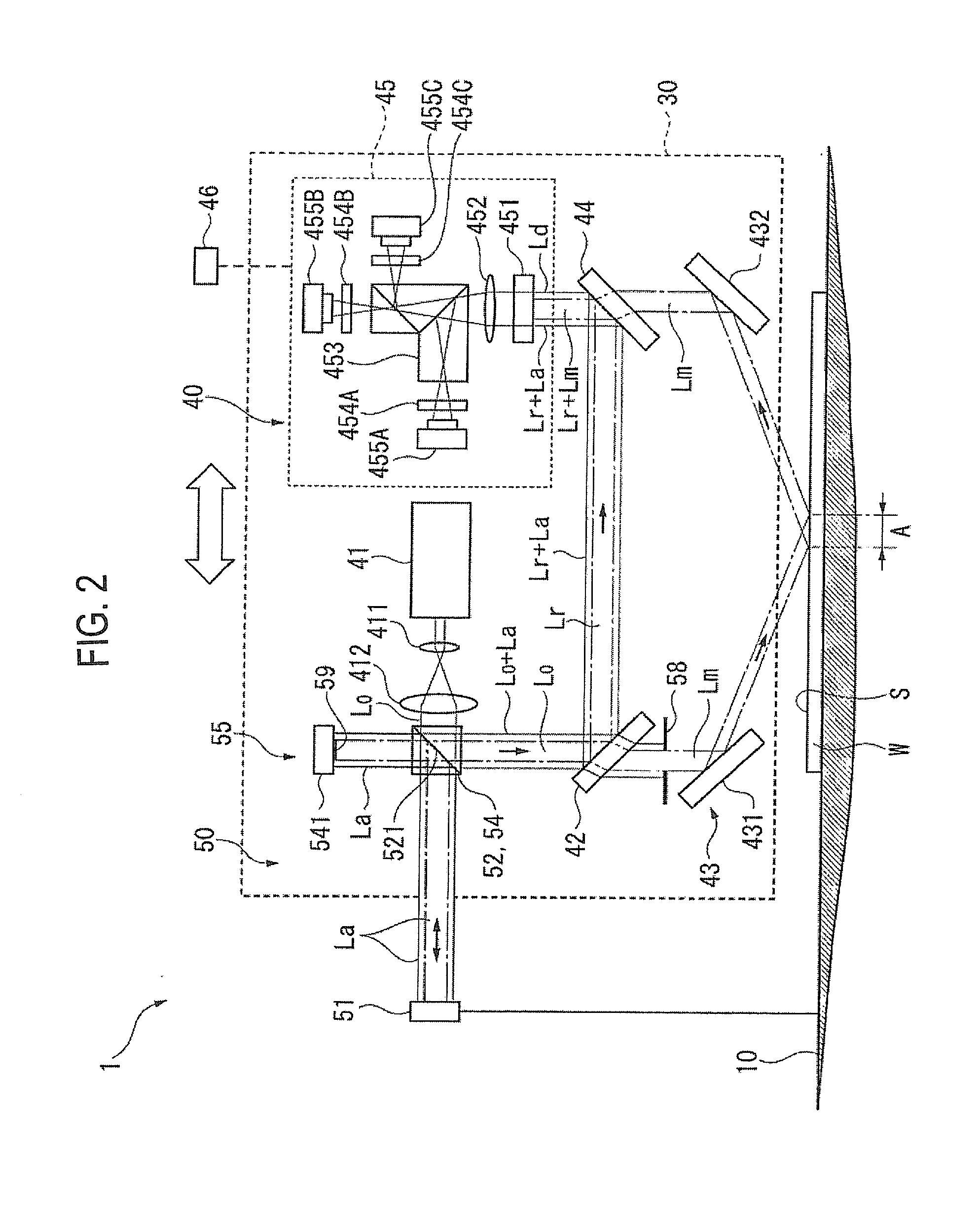
[0138]Like the measuring optical system 40 shown in FIG. 2, the measuring optical system 40A is equipped with the light source 41, the light beam divider 42, the illuminator 43, the light beam combining module 44, and the photodetector 45.
[0139]On the other hand, in the seco...
embodiment 3
[0148]FIG. 12 shows a third embodiment of the invention. As in the second embodiment, a grazing incidence interferometer 1B according to the third embodiment is obtained by modifying the measuring optical system 40 and the auxiliary optical system 50 of the grazing incidence interferometer 1 according to the first embodiment. Different components will be described below with reference to FIG. 12.
[0149]In the third embodiment, a measuring optical system 40B is the same as the measuring optical system 40A used in the second embodiment. The measurement mask 58 is omitted from the measuring optical system 40 shown in FIG. 2 and hence measurement light Lm having the same size as original light Lo is applied to the illuminator 43.
[0150]Furthermore, the light beam divider 42, the light beam combining module 44, and the photodetector 45 do not serve as part of the auxiliary optical system 50B.
[0151]The auxiliary optical system 50B is similar to the auxiliary optical system 50A used in the s...
PUM
Abstract
A grazing incidence interferometer includes a light source, a light beam divider configured to divide original light coming from the light source, an illuminator configured to apply measurement light to a measurement subject, a light beam combining module configured to combine the measurement light reflected from the measurement subject with reference light, and a photodetector configure to detect a combined light beam. The grazing incidence interferometer includes an interferometer main body, a stage configured to hold the measurement subject, a moving mechanism capable of moving the interferometer main body along the measurement subject, and an auxiliary reflector disposed on an extension of an axis of movement of the interferometer main body, an auxiliary light beam separator configured to separate auxiliary light from the original light and to apply the auxiliary light to the auxiliary reflector, and an auxiliary photodetector configured to detect the auxiliary light reflected by the auxiliary reflector.
Description
CROSS-REFERENCE TO RELATED APPLICATION(S)[0001]The present application claims the benefit of priority of Japanese Patent Application No. 2011-140822, filed on Jun. 24, 2011. The disclosures of this application are incorporated herein by reference.BACKGROUND[0002]1. Technical Field[0003]The present invention relates to a grazing incidence interferometer.[0004]2. Related Art[0005]Various interferometers for measuring a surface texture of a workpiece are known, and normal incidence interferometers are commonly used for this purpose. Whereas normal incidence interferometers can perform high accuracy measurement using the wavelength of light as a reference, they cannot measure a texture of a measurement subject having a discontinuous step whose height is larger than half of the wavelength or a large undulation that produces an image having a height variation that is larger than half of the wavelength between adjoining pixels.[0006]Grazing incidence interferometers are known as interferom...
Claims
Application Information
Patent Timeline
Application Date:The date an application was filed.
Publication Date:The date a patent or application was officially published.
First Publication Date:The earliest publication date of a patent with the same application number.
Issue Date:Publication date of the patent grant document.
PCT Entry Date:The Entry date of PCT National Phase.
Estimated Expiry Date:The statutory expiry date of a patent right according to the Patent Law, and it is the longest term of protection that the patent right can achieve without the termination of the patent right due to other reasons(Term extension factor has been taken into account ).
Invalid Date:Actual expiry date is based on effective date or publication date of legal transaction data of invalid patent.

