
Apparatus for capacitive ascertaining and/or monitoring of fill level

Active Publication Date: 2012-01-17
EHNDRESS KHAUZER GMBKH KO KG
View PDF10 Cites 3 Cited by
  • Summary
  • Abstract
  • Description
  • Claims
  • Application Information

AI Technical Summary

Benefits of technology

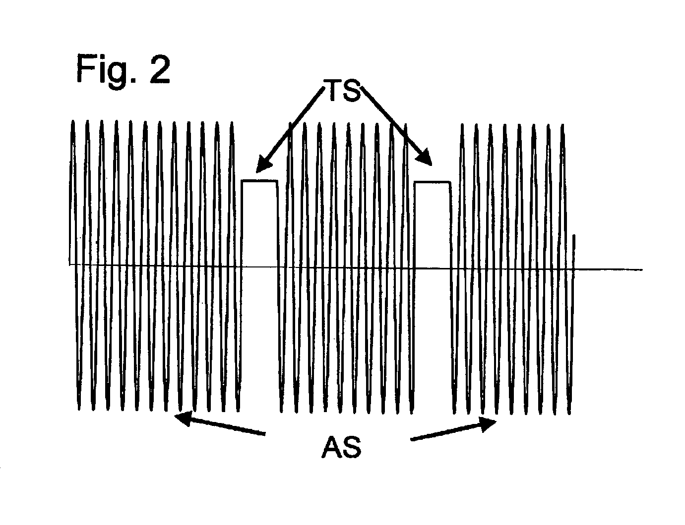
[0006]The invention achieves the object by the features that the electronics unit is embodied in such a manner that it applies the actuating signal to the probe unit in a measuring phase, that it supplies the probe unit with a test signal in a test phase, and that it receives a test measurement signal from the probe unit in the test phase The test signal is embodied in such a manner that it has at least one section with an essentially constant voltage value. The invention thus resides in the feature that the probe unit is operated with two different signals. In a first instance, the operating signal is that for the measuring phase. The signal is an electrical alternating voltage, such as is used in the state of the art for measuring fill level. The second signal, the test signal, is fed to the probe unit during the test phase. This signal is a direct voltage signal. From the test measurement signal resulting therefrom, it can then be concluded whether the insulation is still complete or whether the medium has entered therethrough. For the successful test—i.e. for recognizing that the insulation has been compromised—the probe unit should be contacted by a medium, i.e. the condition should be present, in which the damaged insulation layer or the insulation layer compromised by diffusion degrades the measured value. Thus, the invention permits reliable recognition of damage to the insulation, or diffusion through the insulation, such as can lead to measured value corruption. In this way, also an early recognition (predictive maintenance) of an only slightly damaged probe is possible. This increases the functional safety of the measuring device considerably.
[0012]An embodiment of the invention provides that at least one microprocessor is provided in the electronics unit. A microprocessor simplifies operating the measuring device and offers also the opportunity for directly digitizing the measured signal. Moreover, different measurement or also test procedures can be implemented more easily.

Problems solved by technology

This effect of additional resistance leads to a corruption of the measured value and even to total failure of the measuring device.

Method used


Image

  • Apparatus for capacitive ascertaining and/or monitoring of fill level
  • Apparatus for capacitive ascertaining and/or monitoring of fill level
  • Apparatus for capacitive ascertaining and/or monitoring of fill level

Examples


Embodiment Construction

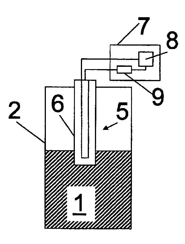
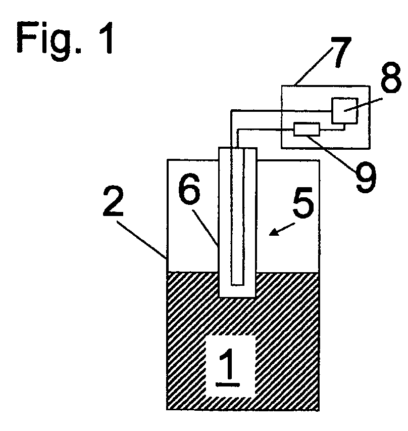
[0017]FIG. 1 shows, schematically, an application of a measuring device of the invention for ascertaining and / or monitoring fill level of a medium 1 in a container 2. Medium 1 is a liquid; it can, however, also be a bulk good. The probe unit 5 (in this instance, a so-called probe rod or probe cable) and the wall of the container 2 form, with the medium 1, a measuring capacitor. Its capacitance depends on the fill level of the medium 1, so that, from the measured capacitance value, fill level can be ascertained. For measuring the capacitance, the probe unit 5 is supplied by the electronics unit 7 with an actuating signal AS. This is usually an electrical, alternating voltage signal of predeterminable frequency. The alternating current signal measured at the probe unit 5 as measurement signal is then usually converted via a resistor (not shown) into a voltage signal and then appropriately evaluated. The electronics unit 7 thus feeds the probe unit 5 with an actuating signal AS, receiv...


PUM


Abstract

An apparatus for capacitive ascertaining and / or monitoring of the fill level of a medium in a container. The apparatus includes at least one probe unit, which is electrically insulated relative to the medium, and at least one electronics unit, which supplies the probe unit with at least one electrical, actuating signal, receives an electrical measurement signal from the probe unit, and evaluates the measurement signal as regards the fill level The actuating signal is an electrical alternating voltage signal. The electronics unit is embodied in such a manner that it supplies the probe unit with the actuating signal in a measuring phase, and supplies the probe unit with a test signal in a test phase, and that it receives a test measurement signal in the test phase from the probe unit, wherein the test signal is selected in such a manner that it has at least one section with an essentially constant voltage value.

Description

TECHNICAL FIELD[0001]The invention relates to an apparatus for capacitive ascertaining and / or monitoring of fill level of a medium in a container.BACKGROUND DISCUSSION[0002]In the case of capacitive fill level measurement or monitoring, a probe unit (for example, a probe rod or a probe cable) and the wall of the container, in which the medium is located, or a second probe unit, form the two electrodes of a capacitor. The medium serves, in such case, as the dielectric. Since the capacitance of the capacitor changes as a function of fill level height, fill level can be deduced from the capacitance. For measuring capacitance, in such case, an actuating signal is fed to the probe unit. This is most often an electrical, alternating voltage of predetermined frequency. Tapped from the “measuring capacitor” is a measurement signal. This is usually an electrical current signal, which is, most often, converted, for example by a resistance element, into a voltage signal for further processing....

Claims


Application Information

Patent Timeline
IPC IPC(8): G01F23/26
CPCG01F23/266G01F25/0076G01F25/0061G01F25/24G01F25/20
Inventor WERNET, ARMINDIETERLE, ROLANDUPPENKAMP, KAJ
Owner EHNDRESS KHAUZER GMBKH KO KG
Learn More