Method of automatically setting vibration suppression filter and automatic setting apparatus for vibration suppression filter

a filter and automatic setting technology, applied in the direction of motor/generator/converter stopper, dynamo-electric converter control, instruments, etc., can solve the problem that the vibration cannot be suppressed while the frequency is analyzed, the operator is difficult to stop the operation, and the vibration is excited or increased on the contrary, so as to reduce the control gain, prevent the effect of enlargement of the vibration and suppress the vibration

Inactive Publication Date: 2009-03-10
YASKAWA DENKI KK
View PDF11 Cites 20 Cited by
  • Summary
  • Abstract
  • Description
  • Claims
  • Application Information

AI Technical Summary

Benefits of technology

[0089]According to the first and fourth aspects of the invention, even when the vibration becomes large due to the automatic setting of the vibration suppression filter, the setting is restored automatically and quickly and so the enlargement of the vibration can be prevented. Alternatively, the vibration can be suppressed by reducing the control gain.
[0090]Further, according to the second and fifth aspects of the invention, even when there are two or more resonance frequencies of the machine, an effective filter setting can be found automatically. Furthermore, even if a vibration frequency not originally existing in the machine arises within the calculation of the frequency analysis, since the setting is not employed, only the effective filter setting can be employed.
[0091]Furthermore, according to the third and fifth aspects of the invention, after detecting the vibration, first, the vibration suppression filer is set based on a result of the frequency analysis according to a method using a part of the data which is not complete in the accuracy but can calculate at a high speed, whereby the abrupt divergence of vibration can be prevented. Further, the vibration suppression filer is set again based on a result of the frequency analysis according to a method using all of the data which takes a long calculation time but is highly accurate, the frequency can be obtained surely and the vibration can be suppressed.

Problems solved by technology

However, in the method of the related art, when the vibration suppression filter is set in the case where the accuracy of the frequency characteristics is bad or there are plural resonance frequencies, there is possibility that the vibration is excited or increased on the contrary.
Further, since the automatic setting starts when the vibration is detected on the way of the operation, it is difficult for an operator to stop the operation when the vibration increases.
Furthermore, since the frequencies are analyzed when the vibration is detected and then the vibration suppression filter is set, the vibration cannot be suppressed while the frequency is analyzed.
Thus, when it takes a long time to analyze the frequencies, the machine may be damaged due to such a phenomenon that the amplitude of the vibration becomes too large before suppressing the vibration.
In contrast, when the number of data for the frequency analysis is reduced in order to reduce the time required for the frequency analysis, the vibration may not be suppressed sufficiently due to such a fact that the frequency detection accuracy is degraded or the frequency detection range is narrowed.

Method used


Image

  • Method of automatically setting vibration suppression filter and automatic setting apparatus for vibration suppression filter
  • Method of automatically setting vibration suppression filter and automatic setting apparatus for vibration suppression filter
  • Method of automatically setting vibration suppression filter and automatic setting apparatus for vibration suppression filter

Examples


first embodiment

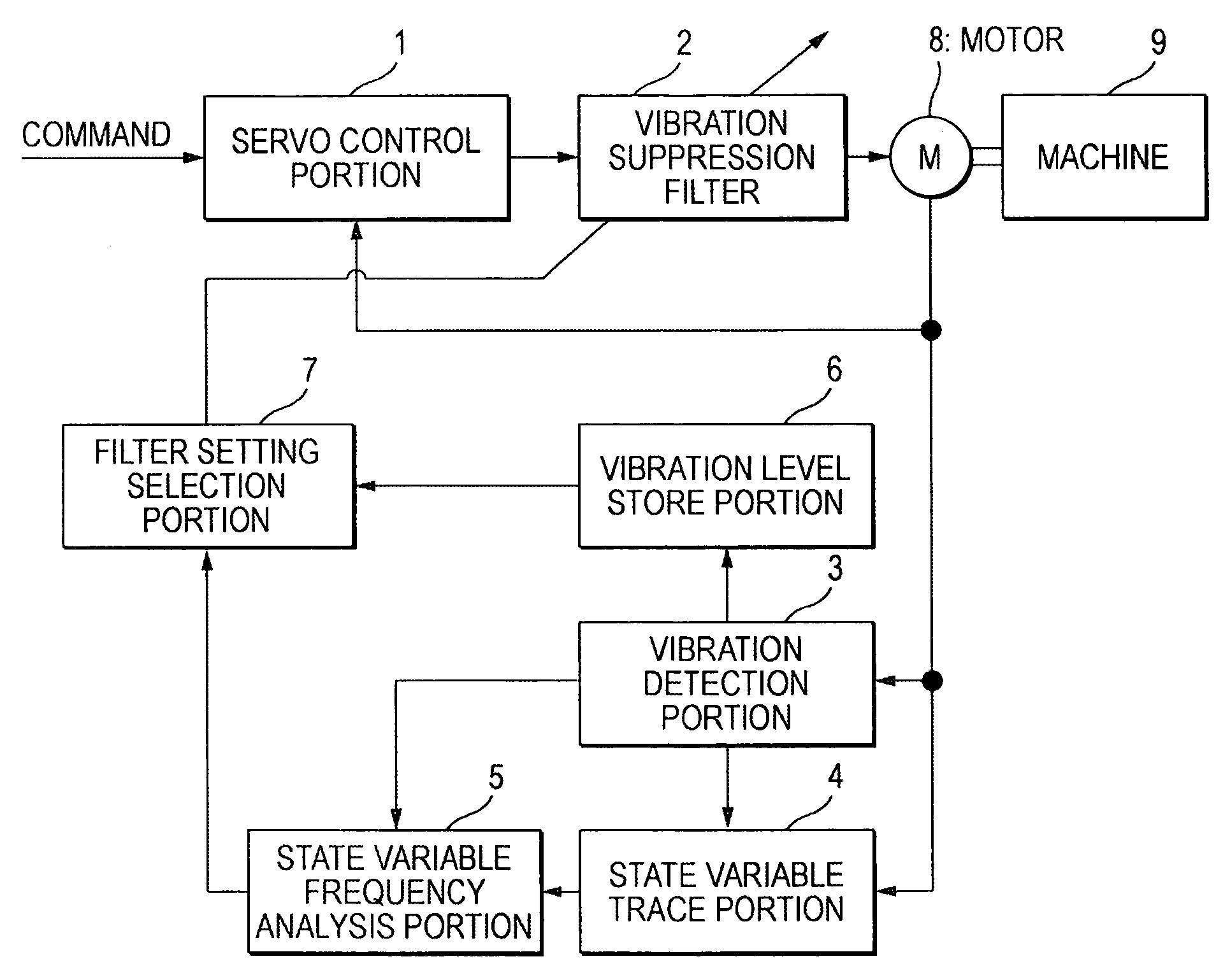
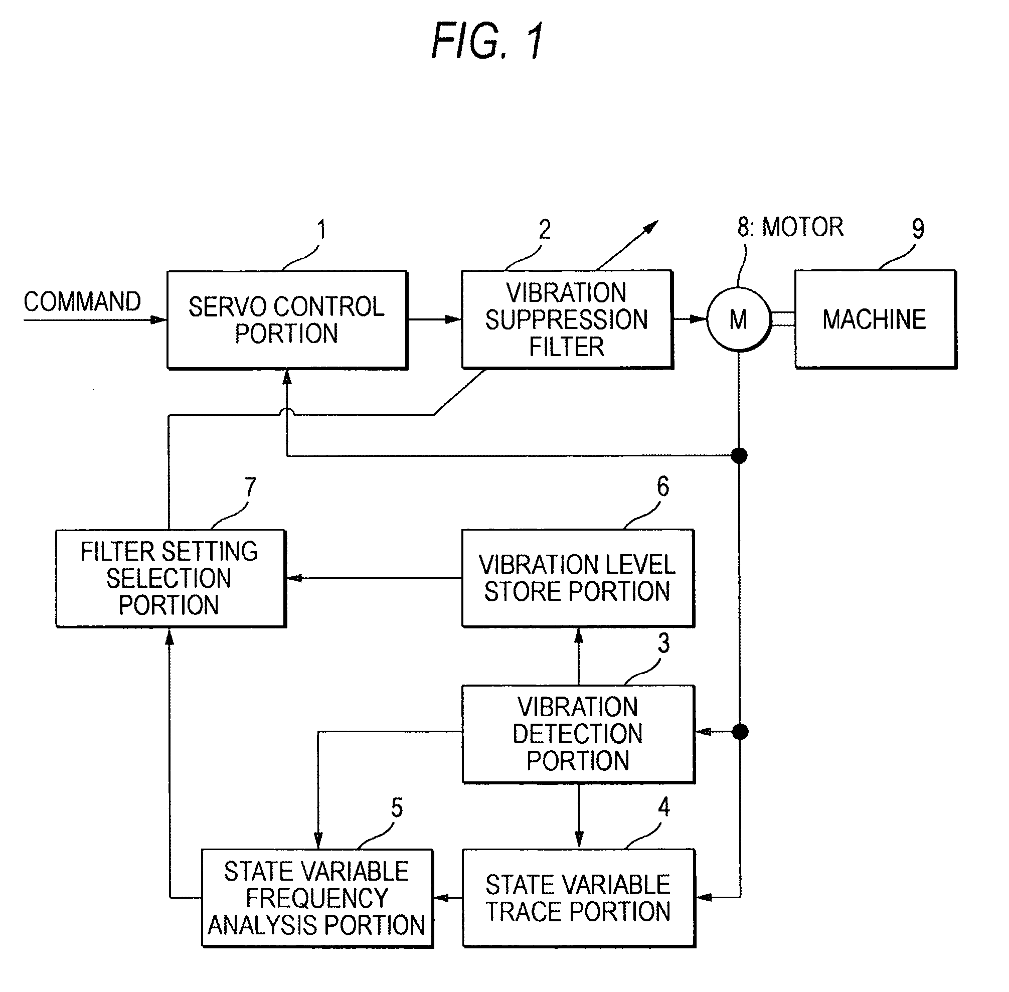
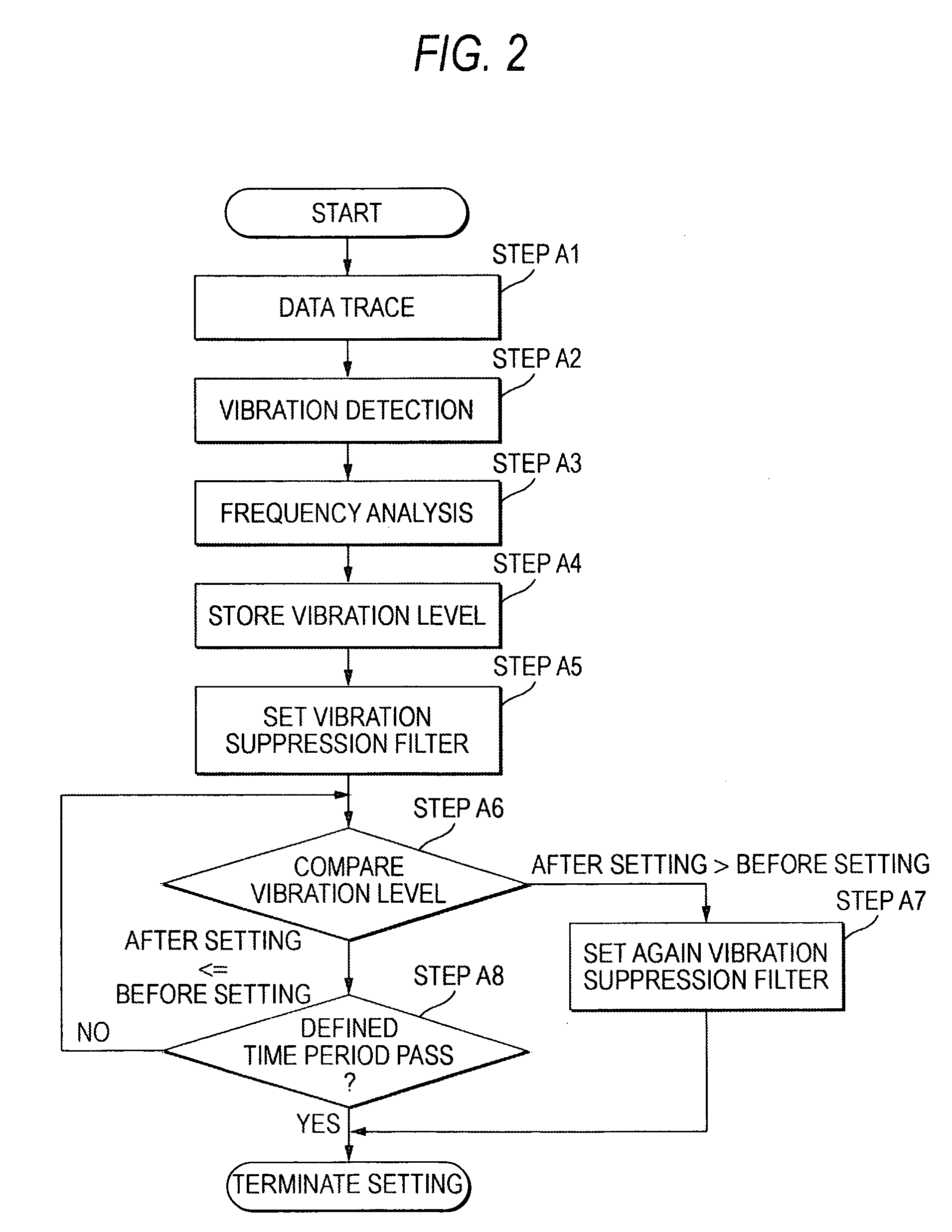
[0109]FIG. 1 is a diagram showing the configuration of the automatic setting method of a vibration suppression filter according to the first embodiment of the invention. FIG. 2 is a flowchart showing the processing of the automatic setting method of the vibration suppression filter shown in FIG. 1. In FIG. 1, a reference numeral 1 depicts a servo control portion, 2 a vibration suppression filter, 3 a vibration detection portion, 4 a state variable trace portion, 5 a state variable frequency analysis portion, 6 a vibration level store portion, 7 a filter setting selection portion, 8 a motor and 9 a machine to be controlled. The motor 8 includes a driver such as a current amplifier and a detector such as an encoder.

[0110]The servo control portion 1 receives a command from a not-shown upper controller and controls a feedback signal from the motor 8 so as to follow the command thereby to operate the machine 9. The command received from the upper controller may be one of a positional com...

second embodiment

[0125]Next, the second embodiment of the invention will be explained based on a drawing.

[0126]FIG. 3 is a flowchart showing the processing of the automatic setting method of the vibration suppression filter according to the second embodiment of the invention.

[0127]The operation according to the second embodiment will be explained based on a flowchart shown in FIG. 3.

[0128]First, in step B1, the time histories such as the feedback signal of the motor are stored in the state variable trace portion 4 while performing the servo control.

[0129]Next, in step B2, the vibration detection portion 3 calculates the vibration level, and determines that the vibration is detected when the vibration level exceeds the threshold value set in advance, whereby the process proceeds to step B3. Step B1 and step B2 may be altered in their order. That is, the data after the vibration detection performed in step B2 may be stored in the state variable trace portion.

[0130]In step B3, the state variable freque...

third embodiment

[0136]Next, the third embodiment of the invention will be explained based on drawings.

[0137]FIG. 4 is a flowchart showing the processing of the automatic setting method of the vibration suppression filter according to the third embodiment of the invention.

[0138]The third embodiment employs the configuration of FIG. 5. That is, FIG. 5 is a diagram showing the configuration of the third embodiment of the invention and has the common configuration as that of the related art of the first and second embodiments. Thus, the configuration of FIG. 5 will be explained again.

[0139]In FIG. 5, a reference numeral 1 depicts a servo control portion, 2 a vibration suppression filter, 3 a vibration detection portion, 4 a state variable trace portion, 5 a state variable frequency analysis portion, 8 a motor and 9 a machine to be controlled.

[0140]The motor 8 includes a driver such as a current amplifier and a detector such as an encoder.

[0141]The servo control portion 1 receives a command from a not-s...


PUM


Abstract

In a method of automatically setting the vibration suppression filter, when a vibration detection portion detects a vibration A2, a state variable frequency analysis portion analyzes the frequencies of data from a state variable trace portion to calculate a vibration frequency A3, and the frequency characteristics of the vibration suppression filter is set based on vibration frequency A5. A vibration level store portion stores the vibration level before the automatic setting of the vibration suppression filter, a filter setting selection portion compares the vibration level after the automatic setting with the vibration level before the automatic setting A6. When the vibration level after the automatic setting is larger than the vibration level before the automatic setting, restoring of the setting of the vibration suppression filter to the state before the automatic setting A7 and / or reducing the gain of a servo control portion.

Description

TECHNICAL FIELD[0001]The present invention relates to a method of, in a servo control apparatus for driving a servomotor, detecting vibration when a machine etc. resonates to automatically set a vibration suppression filter.BACKGROUND ART[0002]For example, in an NC control apparatus of a working machine as shown in a patent document 1, a resonance frequency can be removed in a manner that, as shown in FIG. 7, a signal from a sweep signal generator (1 Hz to almost 100 Hz) 19 coupled to an adder is outputted as a positional command, then a frequency analyzer 20 detects the resonance frequency, and a cut-off frequency variable type notch filter 21 removes the resonance frequency.[0003]According to an improved method of the aforesaid method, the apparatus is operated while sampling data such as a torque or a speed at every time period, then when a vibration detection portion detects a vibration having a pregiven magnitude, then the frequency of the sampled data is analyzed to obtain som...

Claims


Application Information

Patent Timeline
Patent Type & Authority Patents(United States)
IPC IPC(8): G05B5/01G05B13/02G05D3/12G05D19/02H02P23/04
CPCG05B5/01G05B13/024H02P23/04H02P29/0038H02P29/50
Inventor IMADU, ATSUSHITAKEI, YASUYUKITAKAO, KAZUHIDE
Owner YASKAWA DENKI KK
Why Eureka
Try Eureka