Controller for compression ignition engine
a technology of compression ignition and controller, which is applied in the direction of electric control, machines/engines, mechanical equipment, etc., can solve the problems of increasing the mass of nox emission and vibration and noise, increasing noise and vibration, and deteriorating of exhaust gases, so as to prevent the increase in the mass of nox emission and pressure rise rate, prevent the deterioration of exhaust gases, and prevent the effect of increasing vibration and nois
- Summary
- Abstract
- Description
- Claims
- Application Information
AI Technical Summary
Benefits of technology
Problems solved by technology
Method used
Image
Examples
first example
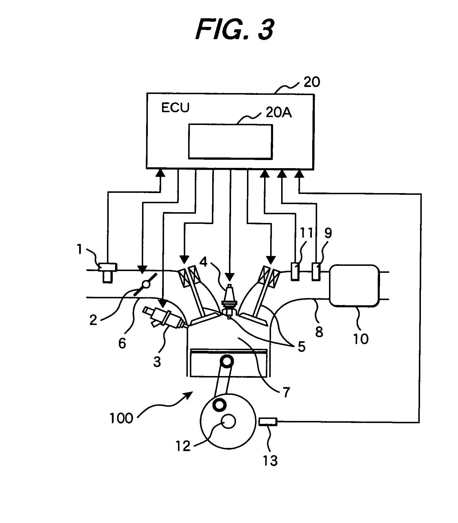
[0035]One example of a first embodiment of the invention will be described below with reference to the accompanying drawings. FIG. 3 shows the first embodiment of the invention, and is a system configuration diagram of a system in which a controller for a compression ignition engine of the embodiment is applied to a gasoline engine for a vehicle.
[0036]An engine 100 is a compression ignition engine which performs spark ignition combustion and HCCI combustion. An air flow sensor 1 for measuring an amount of intake air, and an electronic control throttle 2 for adjusting a flow rate of intake air are disposed in respective appropriate positions of an intake pipe 6. In respective appropriate positions of a cylinder 7 are provided an injector 3 for injecting fuel to a combustion chamber, an ignition plug 4 for supplying ignition energy, and a variable valve 5 for adjusting intake gas flowing into the cylinder, exhaust gas discharged from the cylinder, and the EGR gas in the cylinder. Furt...
second example
[0073]Now, a second preferred embodiment of the invention will be described with reference to the accompanying drawings. The figures showing this embodiment are the same as those of the first embodiment. FIG. 3 shows a system configuration diagram in which a controller of a compression ignition engine of this embodiment is applied to a gasoline engine for a vehicle. The construction and operation of the ECU 20 of the embodiment are the same as those of the first example (see FIG. 6). A combustion mode switching controller 20A is provided for performing the combustion mode switching so as to prevent the deterioration of the exhaust gas and the increase in vibration and noise. Particularly, the combustion mode switching controller 20A of this example corrects the operation amount for the HCCI combustion in the combustion mode switching. Thus, the deterioration of the exhaust gas and the increase in vibration and noise in the combustion mode switching are prevented even when the exhaus...
PUM
 Abstract
Description
Claims
Application Information
 - R&D
- Intellectual Property
- Life Sciences
- Materials
- Tech Scout
- Unparalleled Data Quality
- Higher Quality Content
- 60% Fewer Hallucinations
Browse by: Latest US Patents, China's latest patents, Technical Efficacy Thesaurus, Application Domain, Technology Topic, Popular Technical Reports.
© 2025 PatSnap. All rights reserved.Legal|Privacy policy|Modern Slavery Act Transparency Statement|Sitemap|About US| Contact US: help@patsnap.com


