Advanced portable oxygen concentrator

a portable oxygen concentrator and advanced technology, applied in respirators, separation processes, breathing protection, etc., can solve the problems of affecting the tolerance of sensors, affecting the use of devices, and requiring more than one device to carry, so as to improve the tolerance of sensors and eliminate the hard mounting of sensors

Active Publication Date: 2012-07-05
INOGEN INC
View PDF17 Cites 36 Cited by
  • Summary
  • Abstract
  • Description
  • Claims
  • Application Information

AI Technical Summary

Benefits of technology

[0023]In another embodiment, the portable oxygen concentrator includes a pressure sensor mount where a compliant bracket mounts the pressure sensor and in turn the bracket is mounted to a circuit card. This has the effect of eliminating the hard mounting of the sensor at its designed attachment points, improving the tolerance of the sensor to false readings due to vibration.

Problems solved by technology

Thus portable concentrators involve a significant amount of miniaturization, leading to smaller, more complex designs compared to stationary units, yet they must remain relatively low cost to be available to a wide range of users.
Moreover, the cost constraints of portable concentrators preclude the use of multiple pressure, temperature, and concentration sensors used by large scale industrial concentrators to help optimize efficiency.
One particular challenge of portable concentrator design is that the devices are typically carried by the user.
Prior art portable oxygen concentrators fail to meet all of these design criteria and as a result, the previously available products did not meet all the needs of the users and the home medical equipment providers.
These prior art concentrators failed to meet the users' needs by being too large, too loud, and operated with too much vibration to be near the user 24 hours a day.
These prior art concentrators similarly failed the equipment providers due to frequent malfunctions and short service lives.
The portable nature of the equipment exposes the devices to being dragged over rough roads, bounced around in the trunks of cars, and knocked off counter tops to impact the ground from several feet.
While some prior art equipment might hold up to these high levels of abuse, they do so with added weight and reduced performance parameters such as high noise levels or lowered oxygen flow rates.
Prior art portable oxygen concentrators do not met the objectives of fast and inexpensive repair in the event of damage.
Not only do these assembly methods lead to more expensive repairs, but they limit the scope of facilities that can perform the repairs due to requirements for specific tooling and fixturing that common repair facilities would not have access to.

Method used


Image

  • Advanced portable oxygen concentrator
  • Advanced portable oxygen concentrator
  • Advanced portable oxygen concentrator

Examples


Embodiment Construction

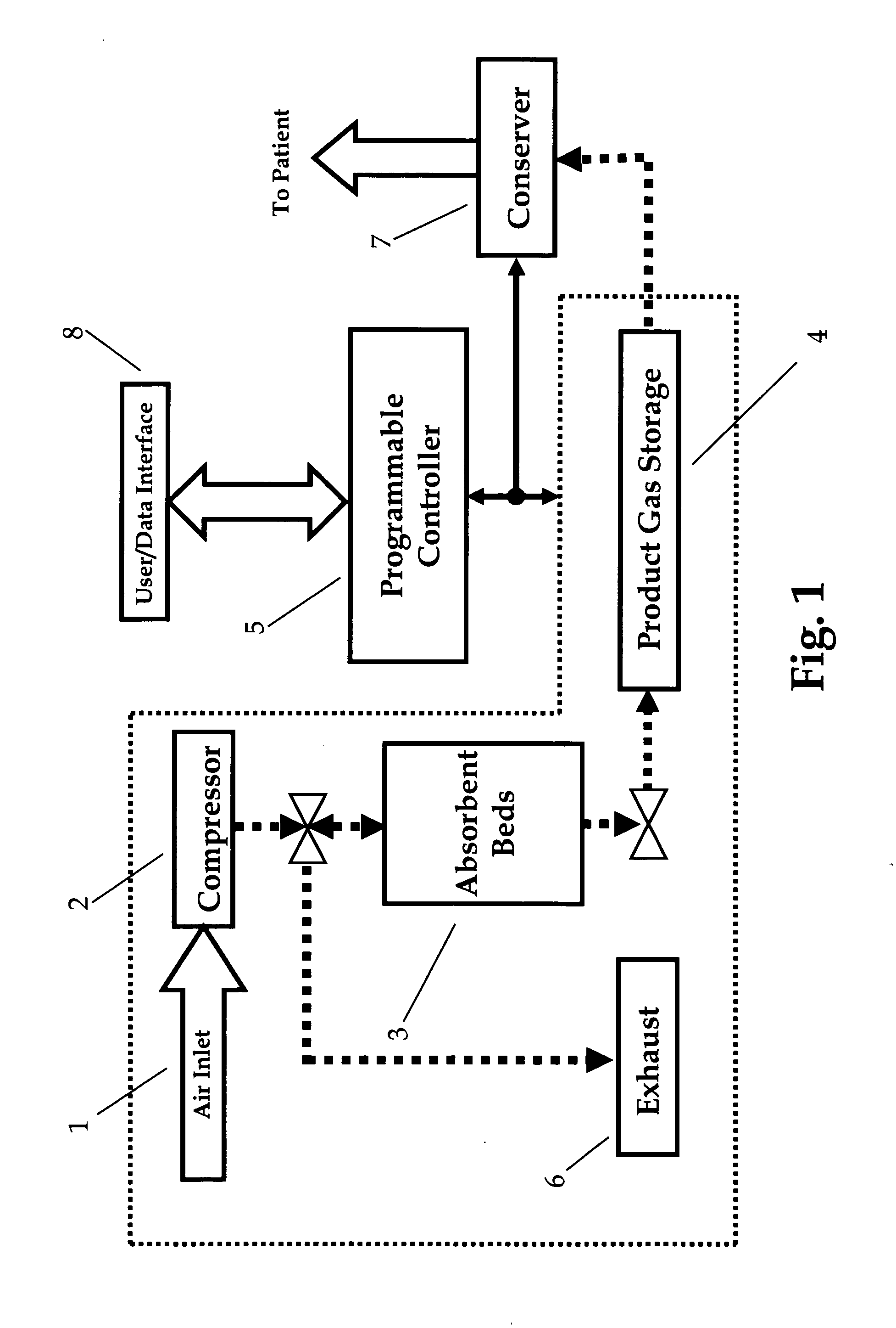
[0032]Referring to FIG. 1, general features of a portable therapeutic gas concentrator are shown. Typically gas is drawn into the inlet through an inlet filter 1 into a compressor 2. Compressed air is then delivered at a rate of about 3 LPM to 30 LPM (through various filters and other devices) to a gas separation section for selectively adsorbing a component of the gas. The preferred embodiments of the invention, although applicable to a variety of gas concentrator implementations, will be described in detail for the case where the inlet gas is air, and the gas separation section is based on PSA, VA, VPSA or some combination thereof, utilizing adsorbent beds 3 which selectively adsorb nitrogen, producing oxygen rich product.

[0033]A variety of gas separation section cycle types and bed arrangements are known in the art, most of which can benefit from the embodiments of the invention. Whatever the details of the gas separation section 3, typically product gas is accumulated in a stora...


PUM

PropertyMeasurementUnit
timeaaaaaaaaaa
pressureaaaaaaaaaa
weightaaaaaaaaaa

Abstract

A portable oxygen concentrator designed for medical use with a novel housing and internal component design that reduces noise and vibration while increasing durability. The improved design of the portable oxygen concentrator further facilitates easy maintenance and repair over the life of the equipment.

Description

RELATED APPLICATIONS[0001]This application is a continuation of U.S. application Ser. No. 12 / 930,256 filed Dec. 30, 2010FEDERALLY SPONSORED RESEARCH[0002]Not ApplicableSEQUENCE LISTING[0003]Not ApplicableBACKGROUND OF THE INVENTION[0004]The inventions generally relates to oxygen concentrators, and more particularly relates to portable medical oxygen concentrators used by patients as a 24 hour a day source of supplemental oxygen.[0005]Portable oxygen concentrators are becoming an increasingly desirable mode of supplying portable oxygen needs to patients requiring Long Term Oxygen Therapy (LTOT). These portable oxygen concentrators are replacing compressed gas cylinders and liquid oxygen systems, which have been the standard of care for many years. Replacing cylinders and liquid oxygen with a portable oxygen concentrator gives a patient the ability to travel onboard aircraft and avoid the requirement to return home to refill a liquid system or exchange empty cylinders. A particularly ...

Claims


Application Information

Patent Timeline
Patent Type & Authority Applications(United States)
IPC IPC(8): A61M16/10
CPCA61M16/10A61M2202/0208A61M2205/42A61M2205/502A61M2205/8206B01D53/0415A61M16/101B01D2253/108B01D2256/12B01D2257/102B01D2259/402B01D2259/4533A61M16/0677B01D53/047A61M16/107
Inventor TAYLOR, BRENTONHANSEN, PETERSTUMP, JOHNBURGESS, PATRICK
Owner INOGEN INC
Why Eureka
Try Eureka