

Hydraulic brake device
a technology of hydraulic brakes and brake pads, which is applied in the direction of brake systems, vehicle components, brake components, etc., can solve the problems of deteriorating reliability, affecting the conformity of electronic parts with the control board, and reducing the durability of joining parts, so as to facilitate the replacement of the ecu
- Summary
- Abstract
- Description
- Claims
- Application Information
AI Technical Summary
Benefits of technology
Problems solved by technology
Method used
Image

Examples
first embodiment
[0027](First Embodiment)
[0028]A hydraulic brake device in the first embodiment according to the present invention will be described hereinafter with reference to the accompanying drawings.
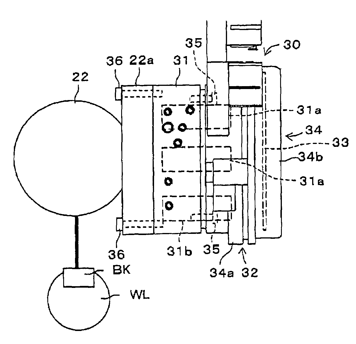
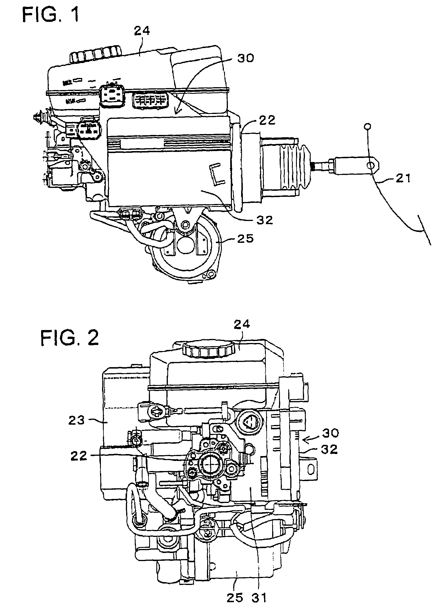
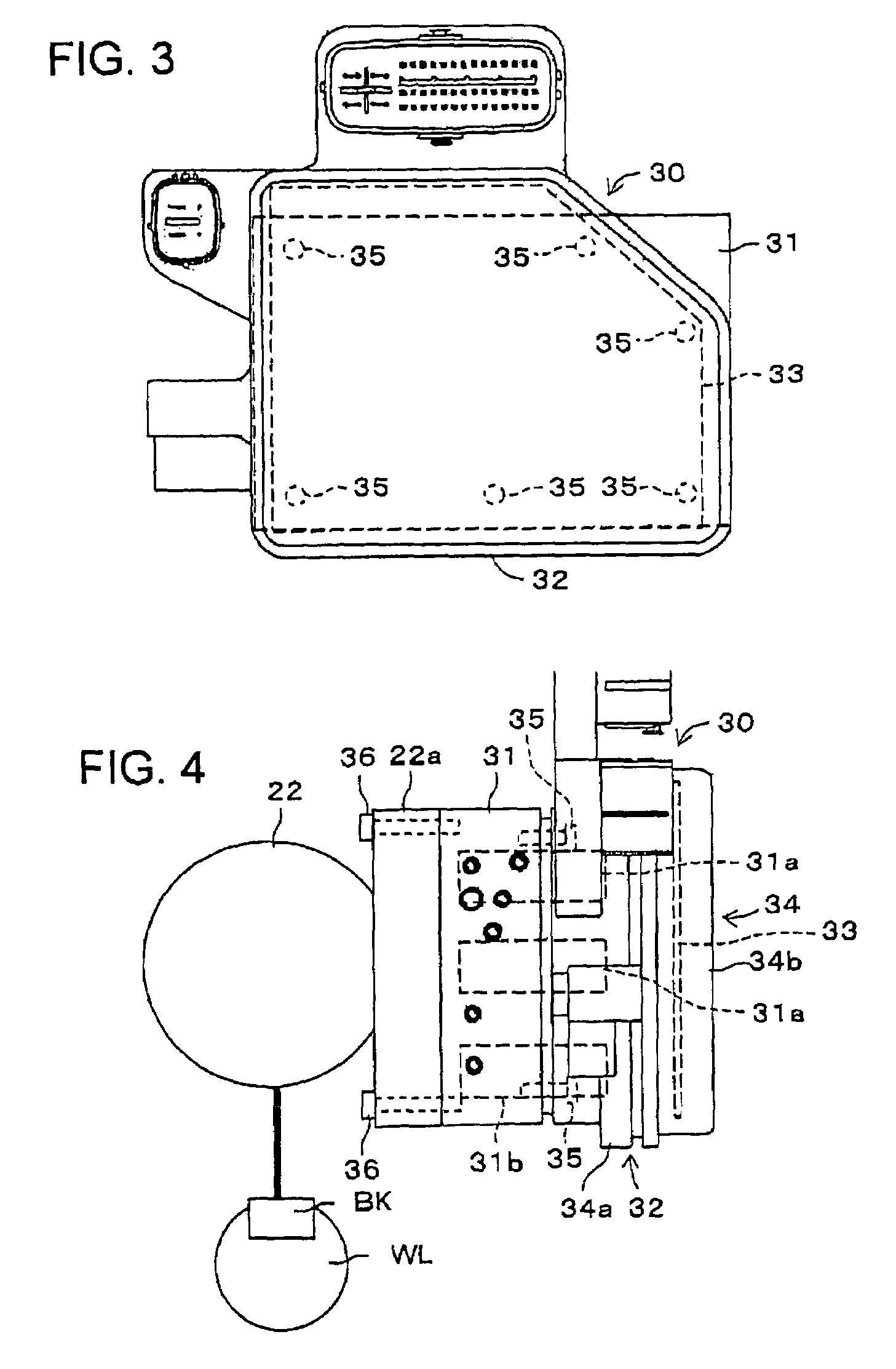
[0029]FIGS. 1 and 2 respectively show a side view and a front view of the general construction of the hydraulic brake device in this first embodiment, and FIGS. 3 and 4 respectively show a side view and a front view of an integrated structure 30 composed of a solenoid block 31 and an ECU (Electronic Control Unit) 32 which are integrated as one body.
[0030]As shown in FIGS. 1 and 4, the hydraulic brake device is provided with a master cylinder 22 constituting a pressurized fluid generator for supplying pressurized fluid to plural brakes (one only shown for simplicity) BK which respectively restrict the rotations of road wheels WL when a brake pedal 21 is stepped on, an accumulator 23 for supplying high pressure brake fluid to augment th pressurized fluid from the master cylinder 22, a reservoir tank ...
second embodiment
[0043](Second Embodiment)
[0044]Next, a hydraulic brake device in the second embodiment according to the present invention will be described with reference to FIG. 6. The hydraulic brake device in the second embodiment is provided with a master cylinder 41 of the vacuum booster type for generating pressurized fluid to be supplied to plural brakes BK which respectively restrict the rotations of road wheels WL when a brake pedal 21 is stepped on, and a hydraulic pump 43a driven by an electric motor 42 which works as pressurized fluid generator for generating pressurized fluid supplied to respective brakes BK independently of the master cylinder 41. The brake device is further provided with an integrated structure 50 mounted on a pump block 43 incorporating the hydraulic pump 43a therein.
[0045]The integrated structure 50 is composed of a solenoid block 51 and an ECU 52 connected with each other and is removably mounted on the pump block 43. Within the solenoid block 51, there are formed...
third embodiment
[0049](Third Embodiment)
[0050]Next, a hydraulic brake device in the third embodiment according to the present invention will be described with reference to FIG. 7. The hydraulic brake device in the third embodiment is provided with a master cylinder 61 for generating pressurized fluid supplied to plural brakes BK which respectively restrict the rotations of road wheels WL, in dependence on a brake manipulation force applied to a brake pedal 21, a hydraulic pump 62c driven by an electric motor 62a in dependence on the applied brake manipulation force for generating pressurized fluid supplied to respective brakes BK independently of the master cylinder 61, and an integrated structure 70 mounted on a pump block 62 incorporating the hydraulic pump 62c therein. The hydraulic pump 62c works as pressurized fluid generator which is provided separated from the master cylinder 61. The pump block 62 is provided with an accumulator 62b for storing the brake fluid that the pump 62c pressurizes w...
PUM
 Abstract
Description
Claims
Application Information