
Novel tube-type oil cooler core clean device

A technology for cleaning devices and oil coolers, which is applied to cleaning methods using liquids, chemical instruments and methods, cleaning methods and utensils, etc., and can solve problems such as inability to thoroughly clean equipment, incomplete cleaning of equipment, and poor heat exchange effect of equipment. , to achieve the effect of being conducive to environmental protection, preventing personnel burns, and high water temperature

Inactive Publication Date: 2013-02-13
CLP CHINA NUCLEAR POWER ENG TECH
View PDF0 Cites 0 Cited by
  • Summary
  • Abstract
  • Description
  • Claims
  • Application Information

AI Technical Summary

Problems solved by technology

[0002] At present, the lubricating oil cooler core (tubular oil cooler) of many power plants has the problem of difficult cleaning, which leads to poor heat exchange effect of the equipment after maintenance due to incomplete cleaning.
Therefore, it is necessary to set up a special cleaning device. At present, the method of flushing with high-pressure water gun and blowing with compressed air is basically used to complete the cleaning work. This type of cleaning method is only suitable for cleaning plate-type oil coolers. Cleaning with this method (tube type) The effect of the oil cooler is poor, and the high-pressure water flow does not go deep into the interior, so it can only clean the copper pipes around the oil cooler, which leads to the disadvantage that the equipment cannot be cleaned thoroughly

Method used


Image

  • Novel tube-type oil cooler core clean device
  • Novel tube-type oil cooler core clean device

Examples


Embodiment 1

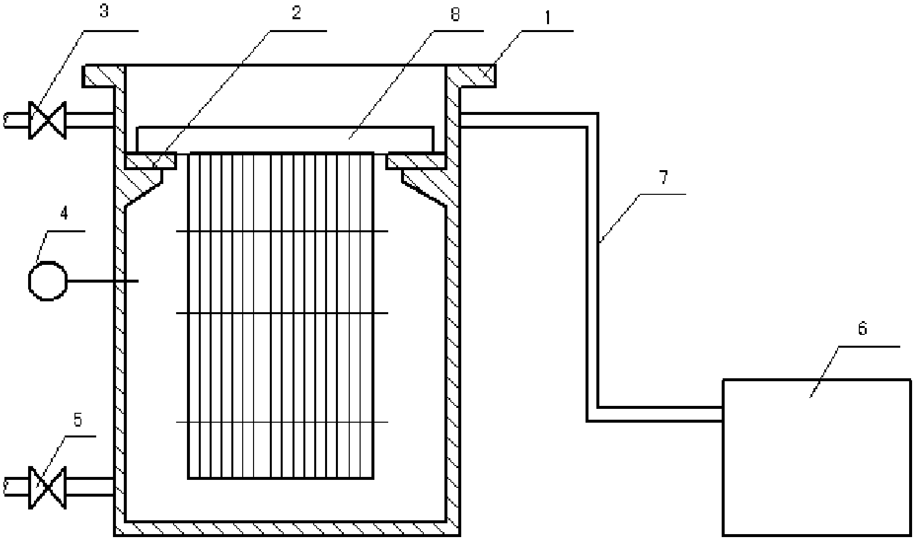
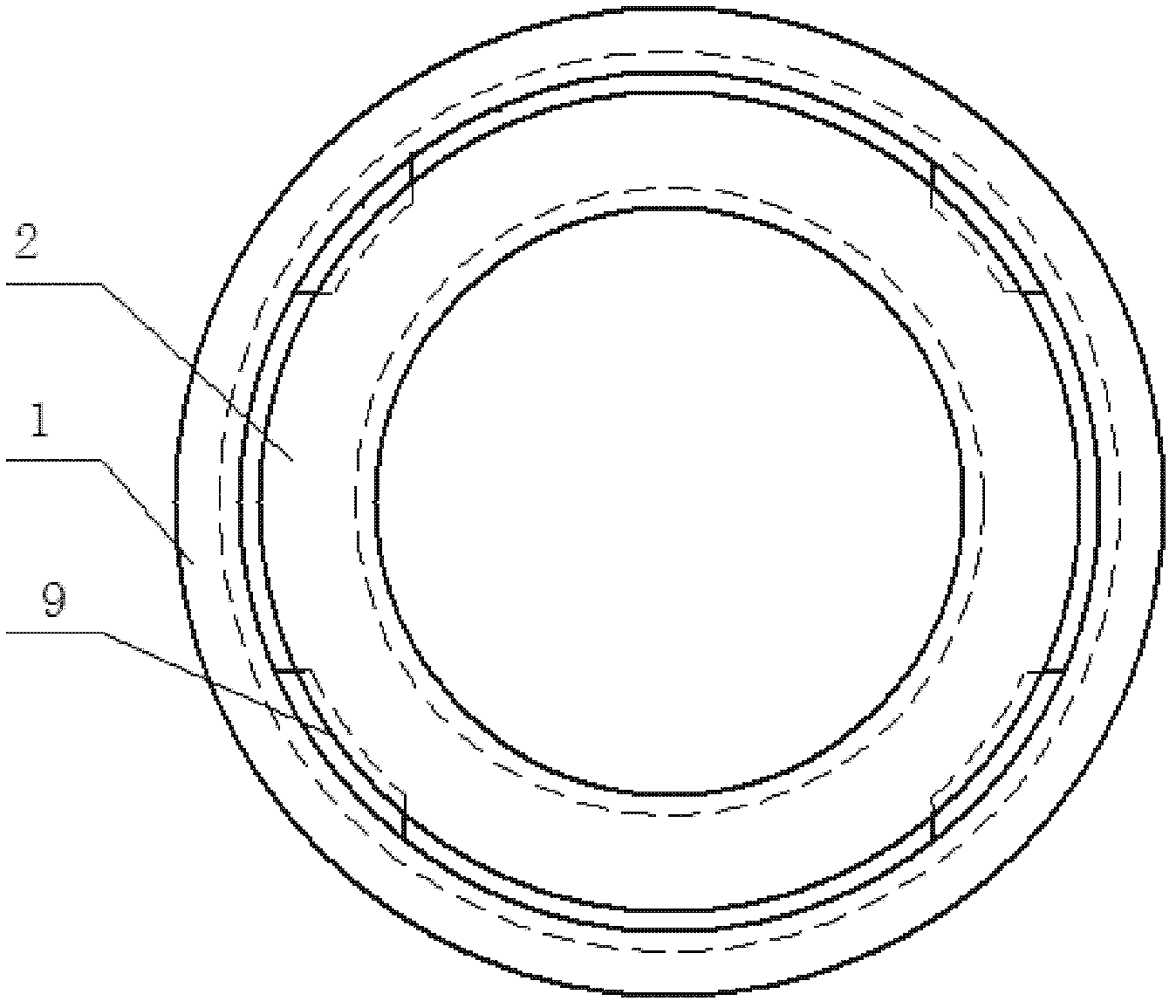
[0020] Such as figure 1 As shown, a new tubular oil cooler core cleaning device, the device includes a cooking cylinder 1, an oil cooler core support ring 2, a water injection valve 3, a thermometer 4, a steam inlet valve 5, and a waste liquid collection box 6. The overflow pipe 7, the water injection valve 3 is connected to the upper part of the boiling cylinder 1 through a pipeline, and injects water into the boiling cylinder, and the steam inlet valve 5 is connected to the lower part of the boiling cylinder 1 through a pipeline, and is used to connect the steam source to the Boiling cylinder, the thermometer 4 is inserted into the boiling cylinder 1 to monitor the temperature change during hot cooking, and the core support ring 2 of the oil cooler is arranged on the inner wall of the special cooking cylinder 1 to play a role in the oil cooler. The core body 8 supports the role of the oil cooler core body 8 when boiling, and the waste liquid collection box 6 is connected to ...


PUM


Abstract

The invention relates to a novel tube-type oil cooler core clean device comprising a boiling tube, a water injection valve, a steam inlet valve, a temperature meter, an overflow pipeline, oil cooler core support rings and a waste liquid collection box, wherein the water injection valve is connected with the boiling tube by a pipeline, the steam inlet valve is connected with the boiling tube by a pipeline, the temperature meter is inserted into the boiling tube, the oil cooler core support rings arranged on the inner wall of the special boiling tube, and the waste liquid collection box is connected with the boiling tube by the overflow pipeline. When the novel tube-type oil cooler core clean device is used for cleaning, an oil cooler core is placed on the oil cooler core support rings, water is injected into the boiling tube by the water injection valve till reaching the mouth of the overflow pipeline, waste liquid is discharged to the waste liquid collection box by the overflow pipeline, steam is charged into the boiling tube by the steam inlet valve, the oil cooler core is continuously boiled for 1-2 days, and at last, the oil cooler core is taken out, flushed and dried. Compared with the prior art, the novel tube-type oil cooler core clean device disclosed by the invention has the advantages of wide range of application, safety, reliability, good cleaning performance, convenience to examination and repair, and the like.

Description

technical field [0001] The invention relates to a cleaning device, in particular to a novel tube-type oil cooler core body cleaning device. Background technique [0002] At present, the lubricating oil cooler cores (tubular oil coolers) in many power plants are difficult to clean, resulting in poor heat transfer effects of equipment after maintenance due to incomplete cleaning. Therefore, it is necessary to set up a special cleaning device. At present, the method of flushing with high-pressure water gun and blowing with compressed air is basically used to complete the cleaning work. This type of cleaning method is only suitable for cleaning plate-type oil coolers. Cleaning with this method (tube type) The effect of the oil cooler is poor, and the high-pressure water flow does not go deep into the interior, so it can only clean the copper pipes around the oil cooler, which leads to the disadvantage that the equipment cannot be cleaned thoroughly. Contents of the invention ...

Claims


Application Information

Patent Timeline
IPC IPC(8): B08B3/00
Inventor 吴刚张伟夏嵩
Owner CLP CHINA NUCLEAR POWER ENG TECH
Learn More