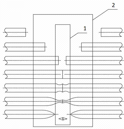
Method for tapering optical fiber preform
An optical fiber preform and taper processing technology, which is used in manufacturing tools, glass fiber drawing devices, glass manufacturing equipment, etc., can solve the problems of excessive glass loss, consumption of glass rods, and low processing efficiency in optical fiber preforms, so as to save processing. Auxiliary materials, beneficial to wire drawing processing, and the effect of improving production efficiency
- Summary
- Abstract
- Description
- Claims
- Application Information
AI Technical Summary
Problems solved by technology
Method used
Image
Examples
Embodiment 1
[0018] Embodiment 1 is a biconical drawing of a solid optical fiber preform with an outer diameter of 180mm.
[0019] Clamp the two optical fiber preforms to the two ends of the glass fusion lathe respectively, so that the axes of the two optical fiber preforms coincide, the two optical fiber preforms rotate synchronously, and ignite the furnace to heat the heat source;
[0020] Move the front sections of the two optical fiber preforms to the furnace 2 for preheating, and the temperature at the front end of the optical fiber preforms reaches about 500°C after preheating for about 15 minutes;
[0021] Move the two optical fiber preforms so that the front ends are close to the heat source 1 in the furnace, and use the heat source to heat the front end faces of the optical fiber preforms;
[0022] After the heat source heats the heating area at the front end of the optical fiber preform to the softening point, the end faces of the two optical fiber preforms are welded together; ...
Embodiment 2
[0026] Embodiment 2 is a biconical drawing of an optical fiber preform sleeve with an outer diameter of 80 mm.
[0027] Clamp the two optical fiber preform sleeves to the two ends of the glass fusion lathe respectively, so that the axes of the two optical fiber preform sleeves coincide, the two optical fiber preform sleeves rotate synchronously, and ignite the furnace to heat the heat source;
[0028] Move the front end of the two optical fiber preform sleeves to the furnace for preheating, and the temperature at the front end of the optical fiber preform sleeve reaches 450°C after preheating for about 5 minutes;
[0029] Move the two optical fiber preform sleeves so that the front ends are close to the heat source in the furnace, and use the heat source to heat the front end faces of the optical fiber preform sleeves;
[0030] After the heat source heats the heating area of the optical fiber preform sleeve to the softening point, the end faces of the two optical fiber sleev...
Embodiment 3
[0034] Embodiment 3 is a biconical drawing of an optical fiber prefabricated core rod with an outer diameter of 40 mm.
[0035] Clamp the two optical fiber prefabricated core rods to the two ends of the glass fusion lathe respectively, so that the axes of the two optical fiber prefabricated rods coincide, the two optical fiber core rods rotate synchronously, and ignite the furnace heating heat source;
[0036] Move the front sections of the two optical fiber core rods to the furnace for preheating, and the temperature at the front end of the optical fiber core rods reaches 500°C after preheating for about 5 minutes;
[0037] Move the front ends of the two optical fiber preform core rods close to the heat source in the furnace, and use the heat source to heat the front end faces of the optical fiber preform core rods;
[0038] After the heat source heats the heating area of the optical fiber preform core rod to the softening point, the two optical fiber preform core rods are ...
PUM
| Property | Measurement | Unit |
|---|---|---|
| Outer diameter | aaaaa | aaaaa |
| Outer diameter | aaaaa | aaaaa |
Abstract
Description
Claims
Application Information
 - R&D Engineer
- R&D Manager
- IP Professional
- Industry Leading Data Capabilities
- Powerful AI technology
- Patent DNA Extraction
Browse by: Latest US Patents, China's latest patents, Technical Efficacy Thesaurus, Application Domain, Technology Topic.
© 2024 PatSnap. All rights reserved.Legal|Privacy policy|Modern Slavery Act Transparency Statement|Sitemap

