
A kind of production method of optical fiber preform cone head

A technology for optical fiber preform and production method, which is applied to manufacturing tools, glass manufacturing equipment and other directions, can solve the problems of waste of optical fiber preform and difficult operation, and achieve the effects of improving the utilization rate of wire drawing, the uniformity of taper, and the improvement of efficiency.

Active Publication Date: 2016-01-06
JIANGSU HENGTONG PHOTOELECTRIC +1
View PDF5 Cites 0 Cited by
  • Summary
  • Abstract
  • Description
  • Claims
  • Application Information

AI Technical Summary

Problems solved by technology

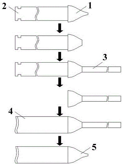
[0004] The invention provides a method for producing the cone head of optical fiber preform, which is used to solve the operation difficulty and waste of optical fiber preform when producing streamline cone head of optical fiber preform, and at the same time reuse the remaining cone head of optical fiber preform remaining after wire drawing

Method used


Image

  • A kind of production method of optical fiber preform cone head

Examples


example 1

[0035] Example 1 is the production of a solid optical fiber preform cone with an outer diameter of 150 mm. (The outer diameter of an optical fiber preform with an outer diameter of 150mm is generally (150±2) mm.)

[0036] Select an optical fiber preform with an outer diameter of 150mm and draw the remaining cone head 1 of the optical fiber preform, and the remaining cone head of the optical fiber preform should be equipped with a tail rod (or tail pipe) 2;

[0037] Cut off the pointed part from the diameter 60mm of the remaining taper 1 of the optical fiber preform drawing with an outer diameter of 150mm;

[0038] Clamp the remaining cone head 1 of the 150mm optical fiber preform with the tail rod (or tail pipe) 2 after cutting and the auxiliary quartz rod 3 with a diameter of 60mm on the chucks at both ends of the glass fusion lathe, light the furnace heat source The end faces of the two are gradually preheated, and the two slowly enter the center of the heat source, burn un...

example 2

[0042] Example 2 is the production of the cone head of a solid optical fiber preform with an outer diameter of 180mm. (The outer diameter of an optical fiber preform with an outer diameter of 180mm is generally (180±2) mm.)

[0043] Select an optical fiber preform with an outer diameter of 180 mm and the remaining cone 1 of the optical fiber preform that has been drawn, and the remaining cone of the optical fiber preform must be equipped with a tail rod (or tail pipe) 2;

[0044] Cut off the pointed part of the remaining taper 1 from the diameter of 70mm for drawing the optical fiber preform with an outer diameter of 180mm;

[0045] Clamp the remaining cone head 1 of the cut 180mm optical fiber preform with the tail rod (or tail pipe) 2 and the auxiliary quartz rod 3 with a diameter of 70 mm at both ends of the glass fusion lathe, and gradually heat the two ends after igniting the furnace heat source. Preheating, the two slowly approach the center of the heat source, burn unt...


PUM

PropertyMeasurementUnit
diameteraaaaaaaaaa

Abstract

A production method for an optical fiber preform conical head comprises: choosing an optical fiber preform with a residual conical head and with a tail rod or a tail tube, wherein the external diameter of the optical fiber preform is n; cutting off the tip portion of the residual conical head from the position with a diameter of m which is also the diameter of an assistant quartz rod; respectively clamping the residual conical head of the optical fiber preform with the tail rod or the tail tube and the assistant quartz rod to clamping heads at two ends, calcining until the residual conical head and the quartz rod are softened, performing butt joint, and cooling; performing cutting on a butt-joint portion between the tail rod or the tail tube and the residual conical head of the optical fiber preform; respectively clamping the optical fiber preform with the external diameter of n and the optical fiber preform residual conical head with the assistant quartz rod to clamping heads at two ends, calcining until the optical fiber preform and the residual conical head are softened, performing butt joint; pointing the center of a heat source at the butt-joint portion between the optical fiber preform residual conical head and the assistant quartz rod and heating, moving the clamps to the opposite directions for pulling the conical head and further for enabling the residual conical head to be a streamline conical head, naturally cooling; and cutting the streamline conical head at a certain external-diameter position, so as to form an optical fiber preform with the streamline conical head.

Description

technical field [0001] The invention relates to the technical field of optical fiber preform rods, in particular to a method for producing a cone head of an optical fiber preform rod. Background technique [0002] The drawing production of optical fiber preform is mainly to use the drawing furnace to heat the optical fiber preform, so that the optical fiber preform is drawn out of the optical fiber from the lower end in the molten state. At the beginning of wire drawing, in order to form a quartz lump at the lower end of the quartz rod, the qualified optical fiber with the core and cladding of the optical fiber preform is pulled out, and the ratio of the core and cladding of the optical fiber is the same as that of the core and cladding of the optical fiber preform. The ratio of the layers is the same, and before the optical fiber preform is drawn, a streamlined cone head is produced at the beginning of the drawing of the optical fiber preform. [0003] In the prior art, th...

Claims


Application Information

Patent Timeline
Patent Type & Authority Patents(China)
IPC IPC(8): C03B37/012
Inventor 任振华肖华沈震强李要飞张献平李晓东田国才时岩
Owner JIANGSU HENGTONG PHOTOELECTRIC
Learn More