Reaction box and construction method of reaction wall

A construction method and technology of reaction force box, which are applied in the processing of building materials, construction, building structure, etc., can solve the problems of delay in construction period, increase in comprehensive cost, accumulated error, etc., to reduce labor, improve positioning and installation accuracy, and improve The effect of installation efficiency

Active Publication Date: 2015-04-29
THE FOURTH OF CHINA EIGHTH ENG BUREAU
View PDF4 Cites 0 Cited by
  • Summary
  • Abstract
  • Description
  • Claims
  • Application Information

AI Technical Summary

Problems solved by technology

[0004] The existing installation method of the loading holes of the reaction box is to adopt the method of adjacent successive positioning and installation, that is, one or a row of loading holes is first positioned on the reaction pedestal of the reaction box, and then according to the positioning of this or this row of loading holes. The next or next row of loading holes adjacent to each other, this method is prone to cumulative errors, resulting in low positioning accuracy of the loading holes, because the positioning of the loading holes of the reaction wall is repositioned according to the position of the loading holes of the reaction box, so There is also a cumulative error; for the installation of the loading hole of the reaction wall, the existing method needs to improve the embedded parts of the loading hole, that is, on the basis of the original design, each end of the embedded part of the loading hole is extended by a specific length, and Pull out the external thread on the extension part, and fix the embedded part of the loading hole on the channel steel bracket with nuts. This process causes a delay in the construction period and an increase in the comprehensive cost of labor, materials and machinery.

Method used


Image

  • Reaction box and construction method of reaction wall
  • Reaction box and construction method of reaction wall
  • Reaction box and construction method of reaction wall

Examples


Embodiment Construction

[0063] The invention provides a construction method of the reaction box and the reaction wall, which improves the positioning and installation accuracy of the loading hole, improves the installation efficiency, and reduces the comprehensive cost.

[0064] The following will clearly and completely describe the technical solutions in the embodiments of the present invention with reference to the accompanying drawings in the embodiments of the present invention. Obviously, the described embodiments are only part of the embodiments of the present invention, not all of them. Based on the embodiments of the present invention, all other embodiments obtained by persons of ordinary skill in the art without making creative efforts fall within the protection scope of the present invention.

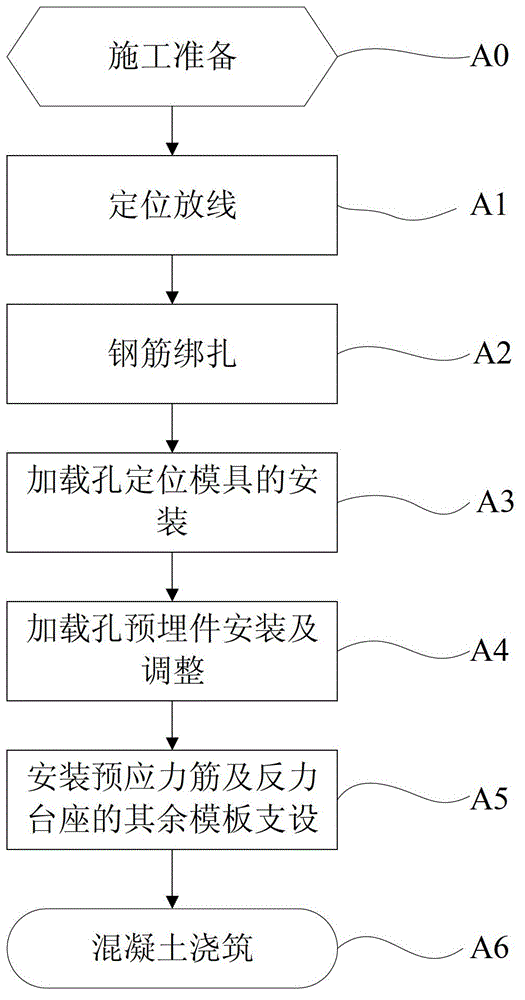
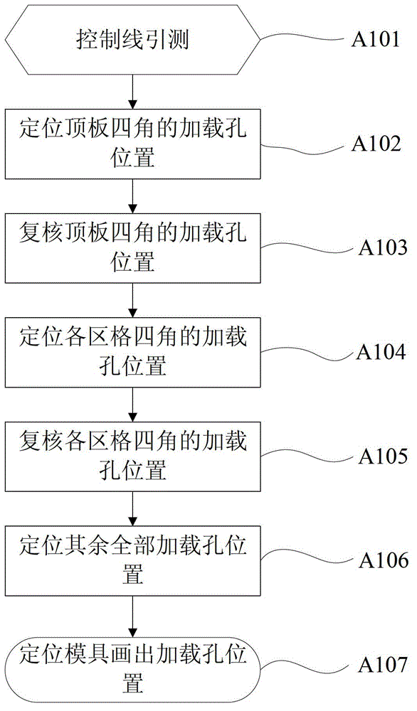
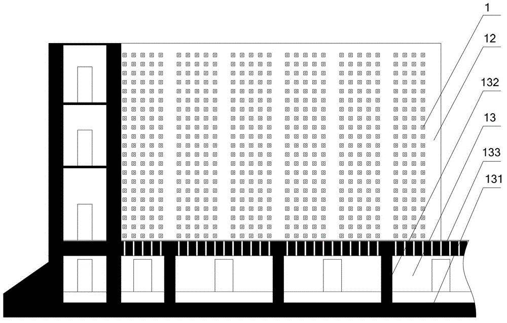
[0065] Please refer to Figure 1-Figure 9 , figure 1 A flow chart of a construction method for a reaction box provided by an embodiment of the present invention; figure 2 A specific flow chart of ...


PUM


Abstract

The invention discloses a construction method of a reaction box, comprising the following steps: staking and layout: firstly locating locations of loading holes located at four corners of a reaction pedestal of the reaction box, then locating locations of the locating holes at four corners of each grid according to the loading hole locations at the four corners of the reaction pedestal, and locating the other loading hole locations in the grid according to the locating hole locations at four corners of the grid; binding reinforcements; mounting locating molds of the loading holes; mounting and adjusting built-in fittings of the loading holes; mounting prestressed tendons, establishing the other templates of the reaction pedestal; casting concrete; and finishing the reaction box construction. By virtue of staking and layout from the whole to the local part, the accumulated error in the existing location is reduced, and the location mounting precision is improved. The invention further discloses a construction method of the reaction wall similar to that of the reaction box. The method does not need to improve the built-in fittings of the loading holes of the reaction wall, so that the mounting efficiency is improved, and the cost is reduced.

Description

technical field [0001] The invention relates to the technical field of building construction, in particular to a construction method of a reaction force box and a reaction force wall. Background technique [0002] The reaction wall test pedestal in the structural laboratory is a test facility for the research of pseudo-dynamic tests, etc. The reaction wall test pedestal includes two parts: the reaction box and the reaction wall. Among them, the reaction box is a cuboid located underground, and the reaction box is composed of a reaction platform, a rib wall, and a bottom plate from top to bottom; Reaction force. Thousands of evenly distributed loading hole embedded parts are pre-embedded in the reaction pedestal and the reaction wall of the reaction box. The loading hole embedded parts are made of steel pipe or steel plate, and the loading hole is formed after concrete pouring. [0003] The center spacing of the loading holes arranged in a matrix is ​​a certain value, and t...

Claims


Application Information

Patent Timeline
Patent Type & Authority Patents(China)
IPC IPC(8): E04G21/00
Inventor 李红德李雪丰叩殿强张鹏飞刘元亮刘民永
Owner THE FOURTH OF CHINA EIGHTH ENG BUREAU
Why Eureka
Try Eureka