Integral blisk flow channel opening coarse plain mounted wrong teeth variable cutting wide disc milling cutter

An integral blisk and runner technology, applied in milling cutters, manufacturing tools, milling machine equipment, etc., can solve the problems of fixed cutting width, low processing efficiency, easy tool wear, etc., to achieve easy accuracy, convenient replacement process, and tool life. improved effect

Inactive Publication Date: 2018-01-19
HARBIN UNIV OF SCI & TECH
View PDF7 Cites 0 Cited by
  • Summary
  • Abstract
  • Description
  • Claims
  • Application Information

AI Technical Summary

Problems solved by technology

[0003] The purpose of the present invention is to solve the problems of low processing efficiency, easy wear of the tool, poor chip removal, fixed cutting width, and high cost in the existing overall blisk slotting, and proposes an integrated blisk flow channel that is rough and flat-mounted. Tooth variable cutting wide disc milling cutter

Method used


Image

  • Integral blisk flow channel opening coarse plain mounted wrong teeth variable cutting wide disc milling cutter
  • Integral blisk flow channel opening coarse plain mounted wrong teeth variable cutting wide disc milling cutter
  • Integral blisk flow channel opening coarse plain mounted wrong teeth variable cutting wide disc milling cutter

Examples


specific Embodiment approach 1

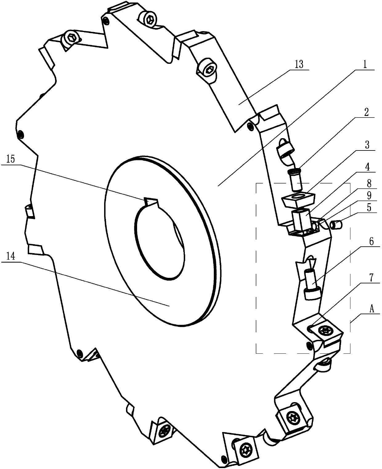
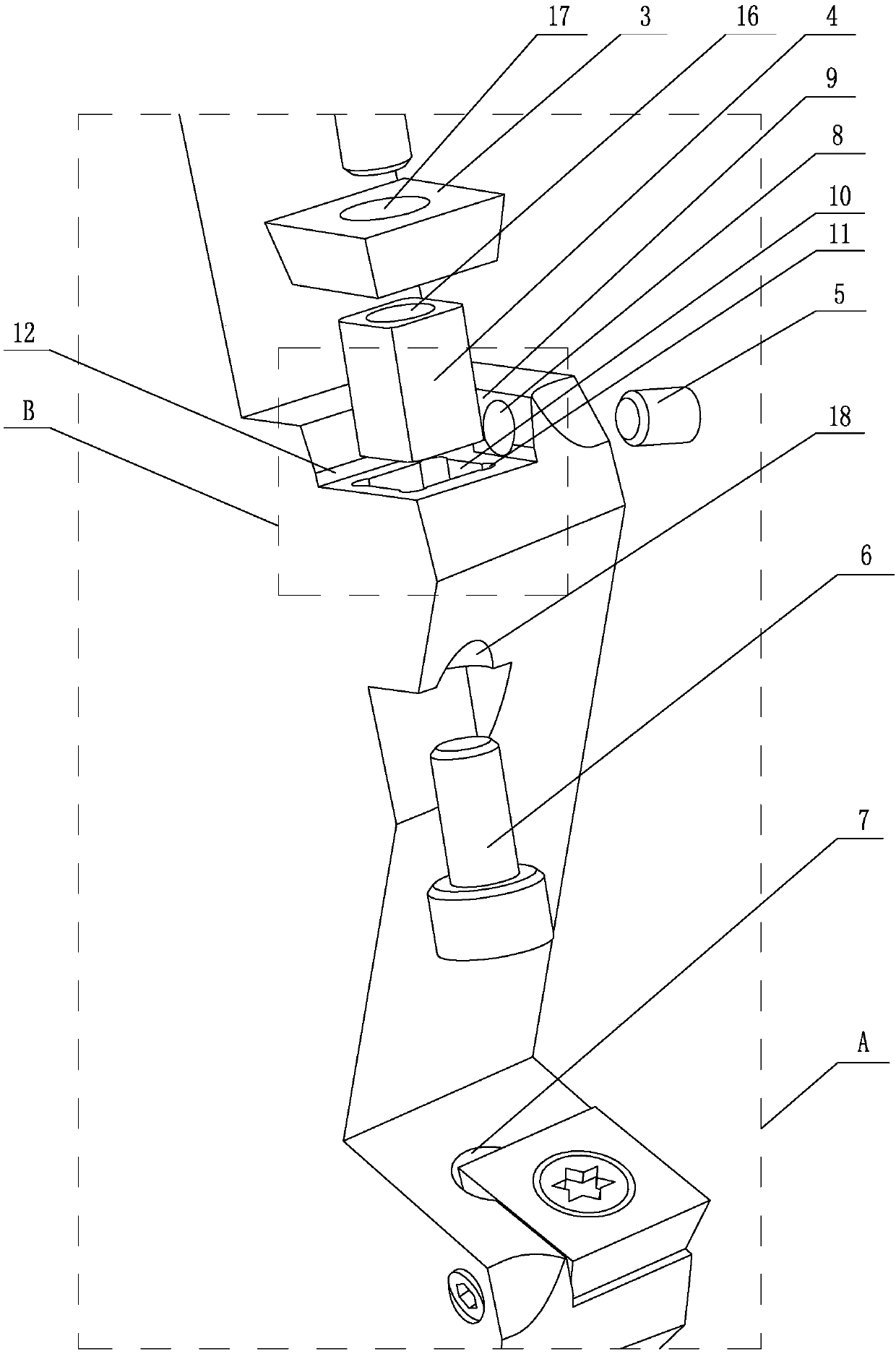
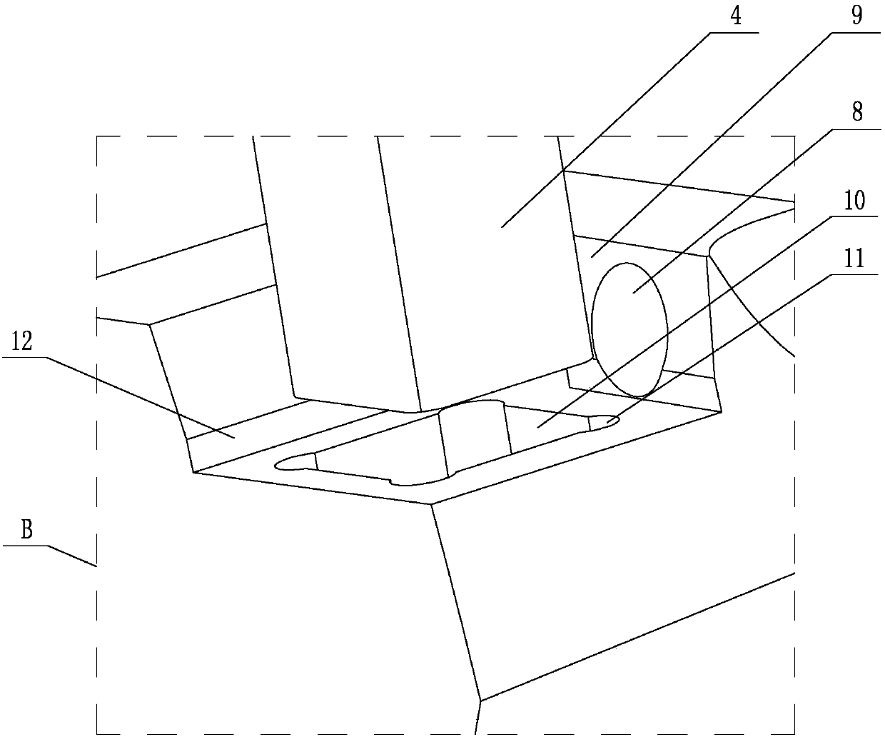
[0021] Specific implementation mode one: as Figure 1~Figure 3 As shown, the overall blisk flow channel is thick and flat-mounted and the variable-tooth variable-cut wide disc milling cutter is composed of a cutter body 1, a central bush 14, a plurality of positioning screws 2 and a plurality of blades 3 (the number of blades 3 is preferably 12), the center of the cutter body 1 is processed with a central through hole, the central bushing 14 is fixedly installed in the central through hole of the cutter body 1, and the inner wall of the central bushing 14 is processed with a keyway 15 along the axial direction, The outer circumferential surface of the cutter body 1 is uniformly processed with a plurality of L-shaped chip removal grooves 13, and the plurality of L-shaped chip removal grooves 13 are all set through the thickness of the cutter body 1, and each L-shaped chip removal groove 13 A sipe 9 is processed on the side of the short groove (preferably the number of sipe 9 is...

specific Embodiment approach 2

[0027] Specific implementation mode two: as Figure 1~Figure 3 As shown in the specific embodiment 1, in the overall blisk flow channel described in the first embodiment, the disc milling cutter with the wrong teeth and variable cutting width is designed, and each of the sipes 9 is designed with a pre-installation angle: that is, the axial rake angle is 4 °~6°, the radial rake angle is 6°~8°, the axial relief angle is 13°~15°, and the radial relief angle is 10°~12°.

specific Embodiment approach 3

[0028] Specific implementation mode three: as figure 1 and figure 2 As shown in the specific embodiment 1, the overall blisk flow channel is thick and flat-mounted with staggered teeth and variable cutting width. .


PUM


Abstract

The utility model relates to a disc milling tool for thickening and flat-mounted staggered teeth of an integral blisk flow channel, which belongs to the technical field of cutting tools. A plurality of L-shaped flutes are evenly distributed on the outer circumference of the cutter body, and a flute is processed on the side of the short flute of each L-shaped flute, and each adjacent two flutes are along the axis of the cutter body. Arranged in a staggered direction, a slider groove is processed on the bottom surface of each groove, a slider is arranged in each slider groove, a blade is arranged in each groove, and each blade is detachably and fixedly connected with the slider , each slider groove is provided with a slider, and there is a gap between each slider groove and the slider in the axial direction, and a tension screw is inserted into the through hole 2 of each slider groove to tighten The screw is tightly connected with the threaded hole 1 of the slider, and a threaded hole 2 is processed on the side wall of the groove perpendicular to the axial direction of each knife groove, and a set screw is screwed in each threaded hole 2, and each Two setscrews axially lean against the corresponding blades. The invention is used for the milling process of the whole blisk.

Description

technical field [0001] The invention relates to a disc milling tool, which belongs to the technical field of cutting tools. Background technique [0002] As an important core structural component of an aero-engine, blisks have complex structures, large blade twists, and poor flow channel opening. Most of the blanks are made of difficult-to-machine materials such as titanium alloys, which brings great difficulty to the manufacture of blisks. The material removal rate is about 60% when the blisk is roughed, so the performance of the roughing tool has a significant impact on the machining efficiency of the blisk. The traditional overall blisk slotting rough machining process mainly uses a ball-end milling cutter to cut the groove shape or use a slotting tool for plunge milling. Large, the tool is easy to break, and the tool has to be replaced, which not only affects the processing efficiency of the blisk but also increases the manufacturing cost. Using a disc milling cutter to...

Claims


Application Information

Patent Timeline
Patent Type & Authority Patents(China)
IPC IPC(8): B23C5/08B23C5/22B23C5/24
CPCB23C5/08B23C5/2239B23C5/2475B23C2210/165B23C5/24
Inventor 程耀楠刘洋陈天启杨金龙
Owner HARBIN UNIV OF SCI & TECH
Why Eureka
Try Eureka