Coupler assembly

A technology for couplings and components, applied in couplings, rigid shaft couplings, machines/engines, etc., can solve the problems of complex assembly and inability to self-lock, and achieve simple assembly, cost saving and low cost Effect

Inactive Publication Date: 2013-02-13
HARBIN DONGAN ENGINE GRP
View PDF5 Cites 8 Cited by
  • Summary
  • Abstract
  • Description
  • Claims
  • Application Information

AI Technical Summary

Problems solved by technology

Flexible couplings generally have axial clearance requirements, and adjustment pads should be provided. Flexible couplings need to be designed with an axial connection structure, and the assembly is more complicated. At the same time, they cannot be locked by themselves, and matching locking measures are required.

Method used


Image

  • Coupler assembly

Examples


Embodiment Construction

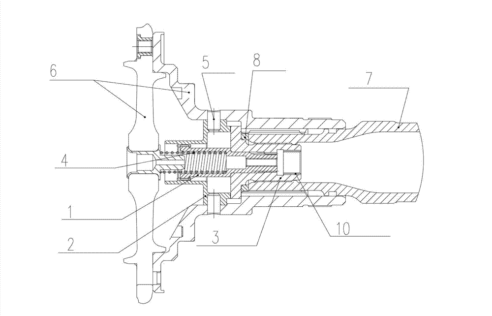
[0010] As shown in the figure, the coupling assembly includes a coupling 1, a housing 2, a screw 3, a pressure spring 4, and an adjusting pad 8. The housing 2 is provided with an internal spline and is fixed on the compressor rotor by a pin 5. 6, the screw 3 is provided with internal splines and fixed with the turbine rotor 7 through external threads, the outer diameter of the coupling 1 is provided with a step for positioning the screw 3, and the inner diameter is provided with a pressure spring 4 positioning steps, the two ends of the coupling 1 are respectively provided with the front outer splines matching the inner splines on the housing 2 and the rear outer splines matching the inner splines on the screw rod 3, the spring The other end of 4 is pressed on the compressor rotor 6, the screw 3 leans against the step provided on the outer diameter of the coupling 1, and an adjusting pad 8 is arranged between the end face of the turbine rotor 7, the said The turbine rotor 7 is...


PUM


Abstract

The invention relates to a coupler assembly. A shell of the coupler assembly is provided with an internal spline and fixedly arranged on a gas compressor rotor through a pin, a screw rod is provided with an internal spline and is fixed with a turbine rotor through external threads, two ends of a coupler are respectively provided with a front external spline matched with the internal spline on the shell and a rear external spline matched with the internal spline on the screw rod, a regulating pad is arranged between end surfaces of the screw rod and the turbine rotor, and the turbine rotor and the gas compressor rotor are in matching connection through splines. The coupler assembly disclosed by the invention has the advantages of compact structure, simpleness in assembly and lower cost, realizes the stable connection after the assembly, and achieves the self locking; and meanwhile, due to the design, the machining accuracy of parts is not too high, and thus the cost is saved.

Description

technical field [0001] The invention relates to a shaft coupling assembly. Background technique [0002] The compressor rotor and high-pressure turbine rotor of an aero-engine are usually connected by a coupling. When the compressor-high-pressure turbine rotor is supported by only two fulcrums, a rigid coupling is generally used, such as the JT9D-74R turbofan engine; when it is supported by three fulcrums, a flexible connector is generally used. Couplings are composed of three structural elements: torque transmission, positioning and fixed connection. [0003] Rigid coupling generally has two ways, the first one is to use pin or key to transmit torsion or select involute spline to transmit torsion, the tooth side is centered or a cylindrical surface is positioned at both ends of the spline, this way can It realizes self-locking, but it needs to set up a special mating surface for centering. At the same time, the torque transmission torque of the pin and the key is small; ...

Claims


Application Information

Patent Timeline
Patent Type & Authority Applications(China)
IPC IPC(8): F16D1/04F02C7/00
Inventor 贺健王学斌陈玉英陶江孙先超陈文鑫
Owner HARBIN DONGAN ENGINE GRP
Why Eureka
Try Eureka