Real-time rendering method based on GPU (Graphics Processing Unit) in binocular system

A real-time rendering, dual-purpose technology, applied in 3D image processing, image data processing, instruments, etc., can solve problems such as high algorithm complexity, bandwidth consumption, and difficulty in applying 3DTV systems

Active Publication Date: 2013-02-13
SHANGHAI UNIV
View PDF1 Cites 11 Cited by
  • Summary
  • Abstract
  • Description
  • Claims
  • Application Information

AI Technical Summary

Problems solved by technology

The image inpainting algorithm can effectively fill the hole in the virtual viewpoint, but its algorithm complexity is extremely high, and it is difficult to apply it to the real-time 3DTV system
In addition, LDI (Layered Depth Image) can also effectively fill holes, which allows holes to be stored in the corresponding layer, so that holes can be filled with these pixels, but LDI not only increases the computational complexity but also consumes a lot of bandwidth.

Method used


Image

  • Real-time rendering method based on GPU (Graphics Processing Unit) in binocular system
  • Real-time rendering method based on GPU (Graphics Processing Unit) in binocular system
  • Real-time rendering method based on GPU (Graphics Processing Unit) in binocular system

Examples


Embodiment 1

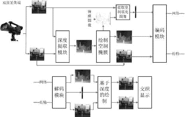
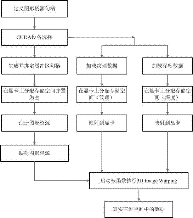
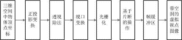
[0028] Referring to Figure 1, the GPU-based real-time rendering method in this binocular system is characterized in that firstly, the hole mask image is drawn at the sending end of the binocular system and the texture information HFI of the large hole is extracted, and then the texture information HFI of the large hole is extracted, and then used at the receiving end of the system to extract HFI fills large holes, and uses interpolation algorithm to fill small holes; in order to meet real-time requirements, GPU is used to accelerate the drawing of virtual viewpoint images; firstly, CUDA technology is used to project pixels in texture images to three-dimensional space, and then Open GL technology is applied Project the pixels in the three-dimensional space to the two-dimensional plane to complete the drawing of the virtual viewpoint image; the steps are:

[0029] (1) The sending end draws the hole mask image and extracts the texture information: draws the hole mask image, uses t...

Embodiment 2

[0033] This example is basically the same as Example 1, and the special features are as follows:

[0034] The specific steps of the step (1) that the sending end draws the hole mask image and extracts the texture information are as follows:

[0035] ① Use the depth image and its corresponding vertex index to perform three-dimensional image transformation. After the transformation, the color buffer is assigned with 0 and 255 respectively, where 0 represents the hole area and 255 represents the non-hole area. According to the storage characteristics of Open GL, the vertex index of the image, the color data of the vertex and the depth information of the vertex are stored in the vertex buffer, the color buffer and the depth buffer respectively; and the hole mask is an image that plays a marking role. It only records the position of the hole without considering the corresponding color data;

[0036] ② Use the hole mask image to find the maximum horizontal value of the large hole, ...


PUM


Abstract

The invention relates to a real-time rendering method based on a GPU in a binocular system. The real-time rendering method comprises the following steps: rendering out a cavity mask image at the sending end of the binocular system and extracting texture information of a large hole; filling the large hole by virtue of the extracted texture information at the receiving end of the system, and using an interpolation algorithm to fill a small hole. According to the invention, the GPU is used to quicken the rendering of a virtual viewpoint image; firstly, a CUDA (Compute Unified Device Architecture) technology is used to project each pixel to a three-dimensional space; and then an OpenGL (Open Graphics Library) technology is used to project the pixel in the three-dimensional space to a two-dimensional plane to finish rendering the virtual viewpoint image. The real-time rendering method greatly improves the rendering speed, and the synthesized novel viewpoint image achieves a good effect on subjective and objective quality, so that real-time rendering of the binocular system can be achieved.

Description

technical field [0001] The invention relates to a rendering technology based on a depth image in a binocular three-dimensional video system, in particular to a real-time rendering method based on a GPU (graphics processor) in a binocular system. Background technique [0002] 3DTV (three-dimensional television) is one of the main applications of stereoscopic display technology. Its typical system components are as follows: video acquisition, encoding and transmission, decoding at the receiving end, 3D (three-dimensional) scene reconstruction and 3D display. The traditional TV system only needs to transmit one channel of video, while the 3DTV system needs to transmit two or more channels of video. However, considering the cost of the camera and the limitation of bandwidth, only a limited amount of video can be transmitted. Therefore, virtual viewpoint drawing at the terminal is very difficult. It is particularly important, and the quality of 3D scene reconstruction is also dir...

Claims


Application Information

Patent Timeline
Patent Type & Authority Applications(China)
IPC IPC(8): G06T15/20
Inventor 郑专安平邬芙琼王奎张兆杨
Owner SHANGHAI UNIV
Why Eureka
Try Eureka