
Horn structure with internal bracket

A technology of inner brackets and speakers, which is applied in the direction of electrical components, sensors, etc., can solve the problems of not being able to take into account the dual enjoyment of vision and hearing, lowering the minimum resonance frequency, and large combined volume

Inactive Publication Date: 2013-02-13
MEILOON INDAL
View PDF4 Cites 11 Cited by
  • Summary
  • Abstract
  • Description
  • Claims
  • Application Information

AI Technical Summary

Problems solved by technology

Although the sound quality of the speaker is good, but the combined volume is relatively large, which is not conducive to the configuration in the LCD TV where the internal storage space becomes very limited. If the speaker is to be barely matched, the size of the speaker must be relatively reduced, but the sound waves emitted by it cannot effectively reduce the minimum resonance. frequency, resulting in unsatisfactory output sound effects, and the inability to take into account the dual enjoyment of vision and hearing, which is its biggest shortcoming

Method used


Image

  • Horn structure with internal bracket
  • Horn structure with internal bracket
  • Horn structure with internal bracket

Examples


Embodiment Construction

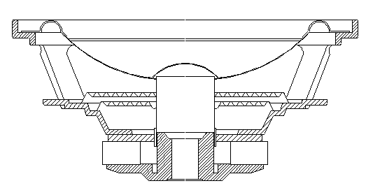
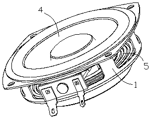
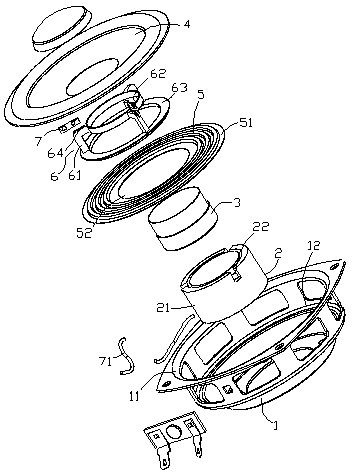
[0025] In order to make a further understanding of the structural composition of the present invention and its operational functions, now cooperate with the drawings to explain as follows; as Figure 2~4 Shown, a kind of inner bracket loudspeaker structure provided by the present invention mainly comprises:

[0026] A housing 1 with an enlarged opening 11 at the front and a magnetic return 2 at the rear;

[0027] a voice coil 3, placed in the middle of the magnetic loop 2, and;

[0028] A vibrating membrane 4, which is placed on the enlarged opening 11 of the casing, and its inner diameter is glued to the voice coil 3;

[0029] Its improved features are:

[0030] A spring wave plate 5, the outer edge 51 is set on the inner step 12 of the shell 1, the inner hole 52 is sleeved on the side wall 21 of the magnetic loop 2, and a plurality of slots 22 are axially spaced above the magnetic loop 2, as well as;

[0031] An inner bracket 6, the upper part is arranged on the side wal...


PUM


Abstract

The invention discloses a horn structure with an internal bracket. The horn structure mainly comprises a shell, a voice coil and a vibrating diaphragm, wherein a dilated opening is formed in front of the shell and a hysteresis loop is accommodated behind the shell; the voice coil is arranged in the middle of the hysteresis loop; the vibrating diaphragm is arranged on the dilated opening of the shell, and the inner diameter of the vibrating diaphragm is adhered with the voice coil. The horn structure is characterized by further comprising an elastic wave plate and the internal bracket, wherein the outer edge of the elastic wave plate is arranged on an inner step of the shell, an inner hole is formed in the side wall of the hysteresis loop in a clearance sleeving manner, and a plurality of profiled grooves are formed above the hysteresis loop in the axial direction at intervals; the upper side of the internal bracket is arranged on the side wall of the voice coil, the lower side of the internal bracket is arranged at the edge of the inner hole of the elastic wave plate, and a plurality of connecting legs which stretch outwards are arranged in the middle of the internal bracket and are over against the upper sides of the plurality of profiled grooves of the hysteresis loop; and therefore, the whole combination height and the size of the horn are effectively reduced, so that the elastic wave plate can be lowered to be arranged on the middle section (or upper edge) of the side wall of the hysteresis loop; and when the voice coil vibrates up and down by assistance of the internal bracket, the plurality of connecting legs can avoid the plurality of profiled grooves above the hysteresis loop; and when the vibration amplitude and the vibration stability of the horn are appropriately increased, and the low-voice response is enhanced so as to improve the sounding quality.

Description

technical field [0001] The invention relates to a horn structure with an inner bracket. More specifically, the simplified design can effectively reduce the overall combination height of the horn and reduce the volume, and use the assistance of the inner bracket to stabilize the vibration of the voice coil and properly strengthen the bass response to improve the quality of pronunciation. Bracket horn structure. Background technique [0002] The design of the new generation of LCD TVs is becoming thinner and thinner, and the volume has been greatly reduced. However, consumers’ requirements for audio-visual quality are increasing day by day. Therefore, the relevant audio-visual equipment not only needs to be high-end, but also the speakers of the terminal output devices. An important factor in determining sound quality. [0003] like figure 1 As shown in the combined structure of the known speaker, an enlarged opening is provided in the front of the housing, and a magnetic re...

Claims


Application Information

Patent Timeline
IPC IPC(8): H04R9/06H04R9/02
Inventor 彭志明周业丰
Owner MEILOON INDAL
Learn More