
Nano-coating thermal barrier and method for making the same

A coating, nanoparticle technology used in the field of controlled thermal energy transfer through materials, which can solve the problems of expensive, time-consuming, not durable enough surfaces for high-performance applications, and achieve light weight effects

Active Publication Date: 2013-02-13
THE BOEING CO
View PDF2 Cites 2 Cited by
  • Summary
  • Abstract
  • Description
  • Claims
  • Application Information

AI Technical Summary

Problems solved by technology

However, the use of layered two-dimensional arrays of small metal particles to reduce heat flow through a phenomenon known as phonon interference has been largely limited to laboratory experiments.
Known layered two-dimensional arrays, which can be time-consuming and expensive to produce and can produce surfaces that may not be durable enough for high-performance applications, such as those found in the aerospace industry

Method used


Image

  • Nano-coating thermal barrier and method for making the same
  • Nano-coating thermal barrier and method for making the same
  • Nano-coating thermal barrier and method for making the same

Examples


Embodiment Construction

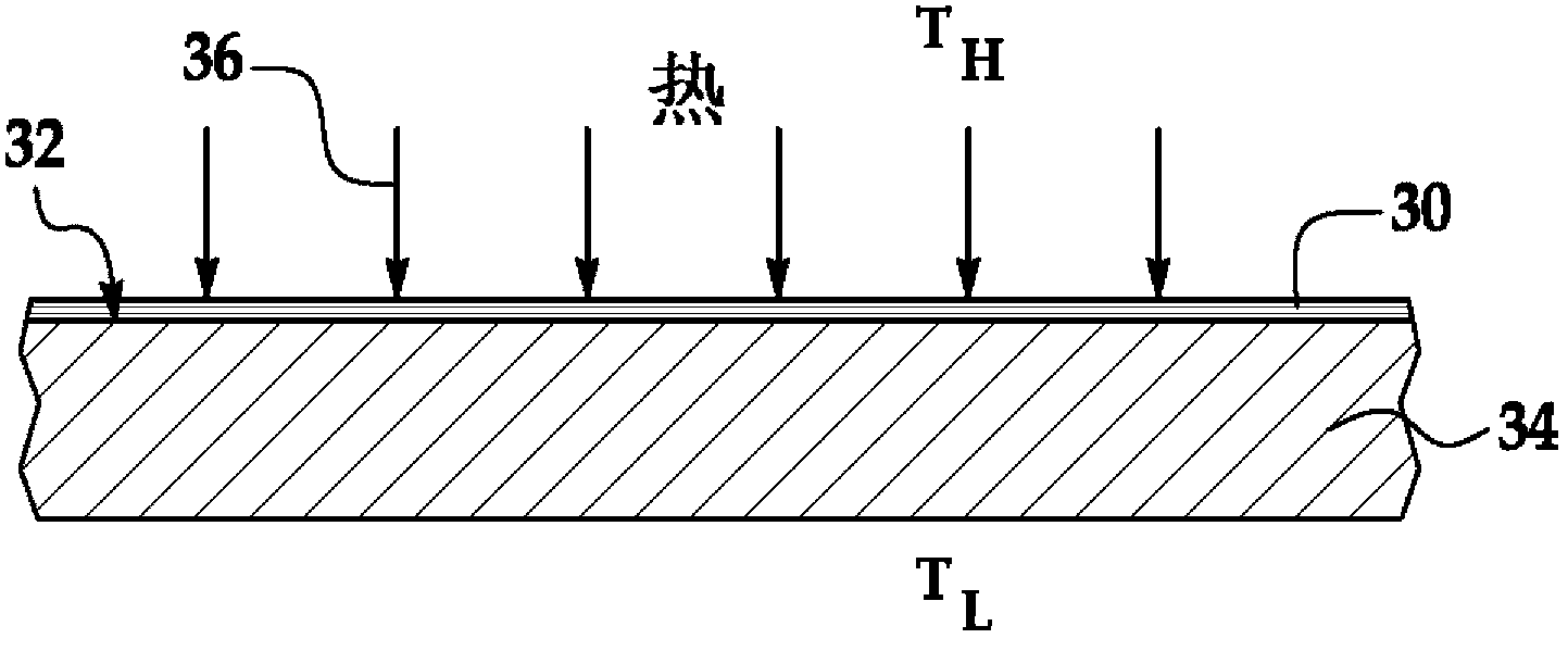
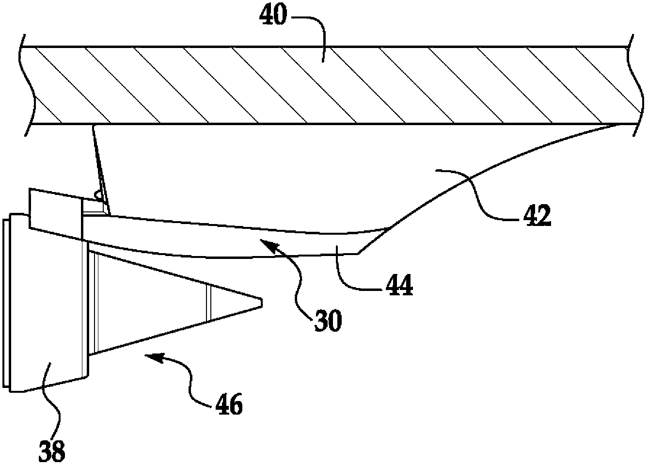
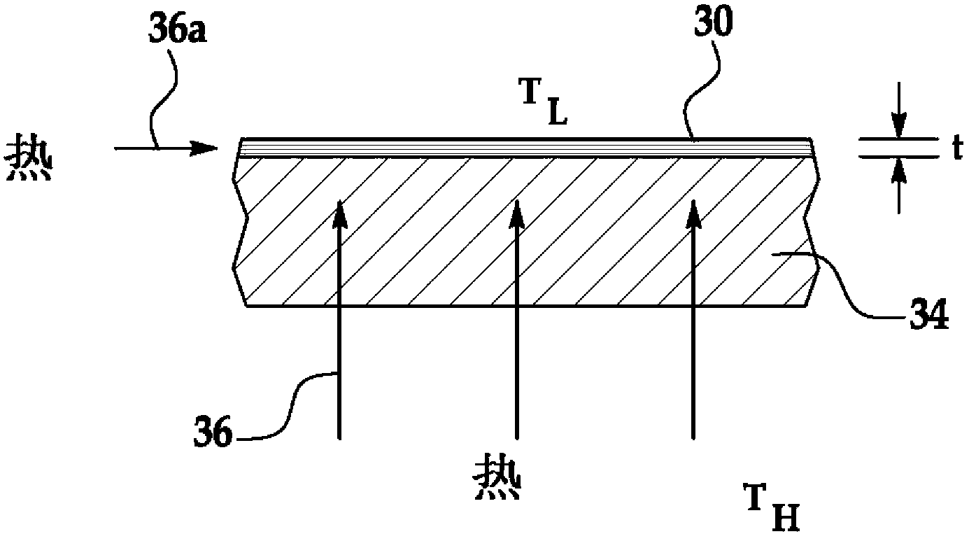
[0162] refer to figure 1 , the disclosed embodiments relate to a thermal barrier coating 30 that may be applied to a substrate 34 in order to control heat 36—also referred to herein as thermal energy—from a higher temperature T H area to lower temperature T L Area delivery. figure 1 In the example shown, thermal barrier coating 30 is designed to reduce the amount of heat 36 reaching substrate 34 . As will be described in more detail below, thermal barrier coating 30 may be a relatively thin, permanent layer, or layer of material that reduces the quantum forms of heat known as phonons by interfering with the flow of phonons through coating 30. The transfer of thermal energy 36 thereby forming a barrier that substantially reduces the transfer of thermal energy 36 to the substrate 34. Phonons are quasiparticles characterized by the quantization of the periodic, lattice vibrational modes of elastic crystal structures in solids. Phonons can be viewed as wave packets with partic...


PUM


Abstract

A coating is adapted to be applied to a substrate for managing the flow of heat traveling through the substrate. The coating comprises an array of metal nano-particles held in a glassy matrix.

Description

technical field [0001] The present disclosure relates generally to techniques for controlling the transfer of thermal energy through materials, and more particularly to thermal barrier coatings and methods for making such coatings. Background of the invention [0002] Managing the flow of thermal energy through materials is important in many industries. Thermal energy flows through the material in the form of thermal quanta known as phonons. The flow of phonons through the material can be reduced by using insulations that present resistance to the flow of phonons, resulting in thermal differentials or temperature gradients. However, the use of spacers to control thermal energy transfer may have limitations in some applications. For example, in the aerospace industry, the use of spacers to reduce thermal energy transfer may add undesired weight to the vehicle, or may result in parts that are too large or thick for the application. [0003] The flow of phonons through the m...

Claims


Application Information

Patent Timeline
Patent Type & Authority Applications(China)
IPC IPC(8): C23C24/10B22F1/00B22F1/02C03C8/18
CPCF28F2255/20Y02T50/67C04B35/581C23D5/04B22F2998/10F28F2255/06B22F1/02C04B2235/404C04B2235/3895C23C24/10B22F1/0003C03C8/18C04B2235/405C23D5/00F28F2270/00F28F13/185B22F1/054B22F1/16B22F1/107Y02T50/60
Inventor J·C·拉塞尔T·L·怀特B·史夫利特P·凯里尼特S·瓦德里C·巴恩哈特V·赫吉科夫K·纳卡摩德
Owner THE BOEING CO
Learn More