Pressure relief device

A technology of pressure relief device and pressure relief wheel, which is applied in textiles, textiles, papermaking, looms, etc., can solve the problems of unset and poor weaving effect, and achieve good results

Inactive Publication Date: 2013-02-20
SUZHOU HUALONG KNITTING TEXTILE
View PDF8 Cites 1 Cited by
  • Summary
  • Abstract
  • Description
  • Claims
  • Application Information

AI Technical Summary

Problems solved by technology

[0002] In the prior art, there is usually no pressure relief device on the loom, and the weaving effect is poor

Method used


Image

  • Pressure relief device
  • Pressure relief device
  • Pressure relief device

Examples


Embodiment Construction

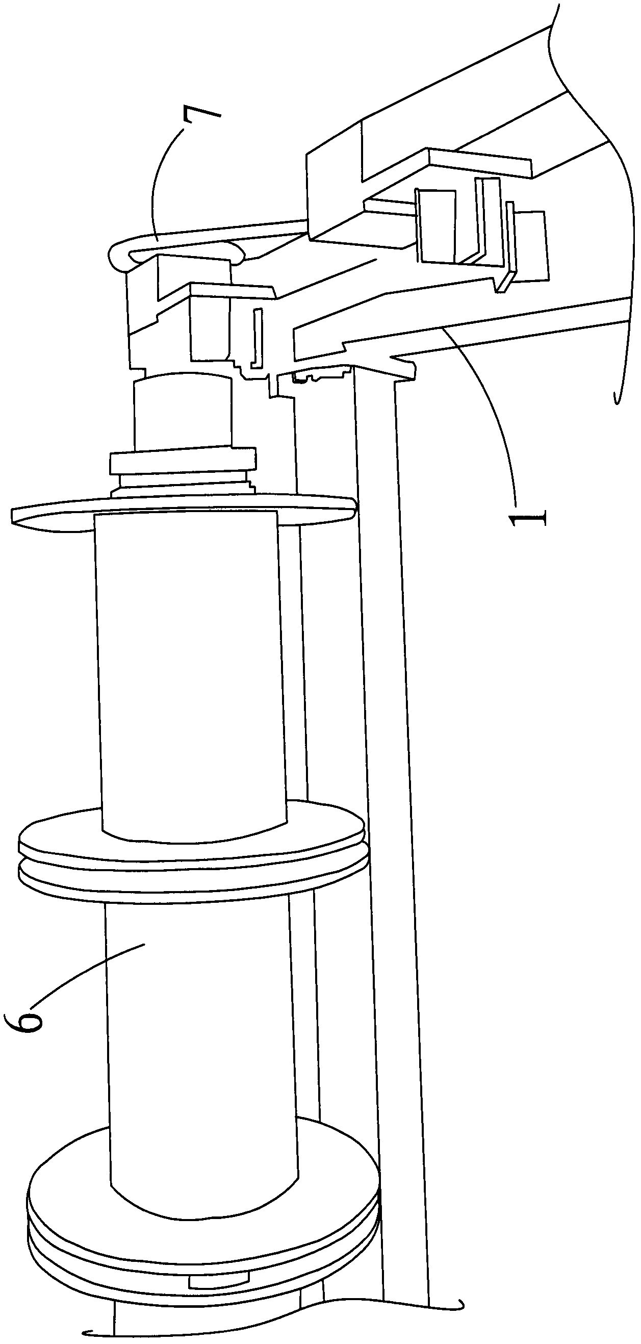
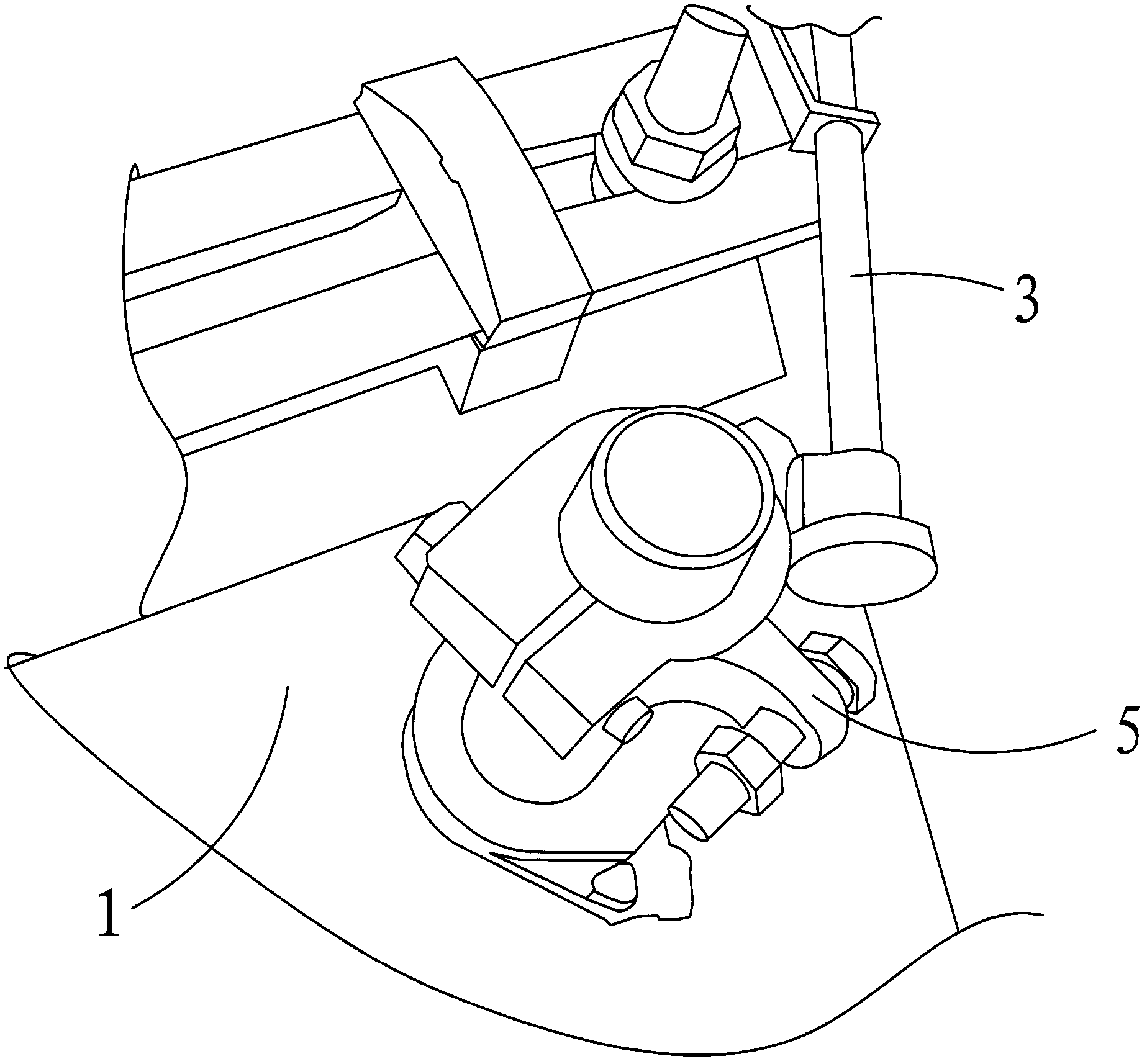
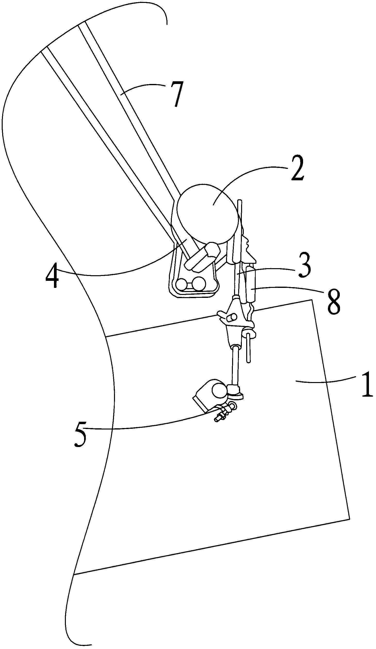
[0014] as attached figure 1 - attached image 3 As shown, a pressure relief device includes a pressure relief wheel 2 rotatably arranged on the frame 1, a slide bar 3 slidingly provided with the frame 1, and one end of the slide bar 3 The connected pull belt 4, the block 5 fixedly arranged on the frame 1 for conflicting with the slide bar 3, the other end of the pull belt 4 is in contact with the machine The frame 1 is fixedly arranged, and the pulling belt 4 is connected to the sliding bar 3 by bypassing the pressure relief wheel 2, and the frame 1 is rotatably provided with a mounting bracket for installing the knitting thread. frame 6, and a transmission mechanism is set between the mounting frame 6 and the pressure relief wheel 2.

[0015] The transmission mechanism includes the first gear set on the mounting frame 6, the second gear set on the pressure relief wheel 2, and the first gear and the second gear respectively Interlocking chains7.

[0016] The sliding direct...


PUM


Abstract

Disclosed is a pressure relief device. The pressure relief device comprises a pressure relief wheel, a sliding bar, a tractive band and an abutting block, the pressure relief wheel is rotatably arranged on a rack, the sliding bar is arranged with the rack in a sliding mode, one end of the tractive band is connected with the sliding bar, the abutting block is fixedly disposed on the rack and used for abutting to the sliding bar, the other end of the tractive band is fixedly arranged with the rack, the tractive band bypasses the pressure relief wheel to be connected with the siding bar, a mounting frame for mounting knitting threads is rotatably mounted on the rack, and a transmission mechanism is arranged between the mounting frame and the pressure relief wheel. By means of the pressure relief device, the effect of weaving cloth is good.

Description

technical field [0001] The invention relates to a pressure relief device. Background technique [0002] In the prior art, the loom is usually not provided with a pressure relief device, and the weaving effect is relatively poor. Contents of the invention [0003] The technical problem to be solved by the present invention is to provide a pressure relief device. [0004] In order to solve the above-mentioned technical problems, a technical solution adopted by the present invention is: a pressure relief device, including a pressure relief wheel rotatably arranged on the frame, a slide bar slidably provided with the frame, and a part of the pull belt connected to the slide bar, a block fixed on the frame for conflicting with the slide bar, the other end of the pull belt is connected to the The frame is fixedly arranged, and the pulling belt is connected to the slide bar by going around the pressure relief wheel, and the frame is rotatably provided with a mounting frame for ...

Claims


Application Information

Patent Timeline
Patent Type & Authority Applications(China)
IPC IPC(8): D03D49/06
Inventor 胡永明
Owner SUZHOU HUALONG KNITTING TEXTILE
Why Eureka
Try Eureka