Tension control mechanism

A tension mechanism and frame technology, applied in textiles and papermaking, weft knitting, knitting, etc., can solve problems such as poor weaving effect and achieve good effect.

Inactive Publication Date: 2013-02-20
SUZHOU HUALONG KNITTING TEXTILE
View PDF6 Cites 1 Cited by
  • Summary
  • Abstract
  • Description
  • Claims
  • Application Information

AI Technical Summary

Problems solved by technology

[0002] In the prior art, there is usually no tension control mechanism on the loom, and the weaving effect is poor

Method used


Image

  • Tension control mechanism

Examples


Embodiment Construction

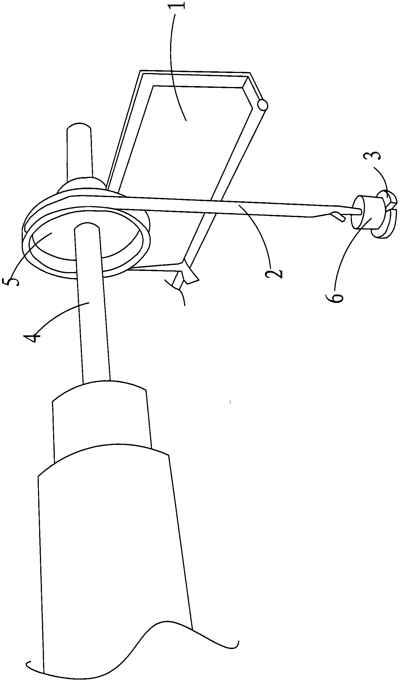
[0010] as attached figure 1 As shown, a tension control mechanism includes a pulling belt 2 fixedly connected to the frame 1 at one end, and a connecting frame fixed to the other end of the pulling belt 2 for installing a weight 6 3. The pulling belt 2 goes around the installation shaft 4 for winding the knitting thread, and the installation shaft 4 is set in rotation with the frame 1 .

[0011] A mounting frame 5 for the pulling belt 2 is fixedly arranged on the mounting shaft 4 .

[0012] As mentioned above, we have fully described according to the purpose of the present invention, but the present invention is not limited to the above-mentioned embodiments and implementation methods. Practitioners in the relevant technical fields may make various changes and implementations within the scope permitted by the technical ideas of the present invention.


PUM


Abstract

A tension control mechanism comprises a traction band with one end fixedly connected with a machine frame and a connection frame fixedly connected with the other end of the traction band and used for weights to be placed on. The traction band winds around an installation shaft used for knitting lines to be wound on, and the installation shaft rotates relative to the machine frame. The tension control mechanism enables weaving effect to be good.

Description

technical field [0001] The invention relates to a tension control mechanism. Background technique [0002] In the prior art, the loom is usually not provided with a tension control mechanism, and the weaving effect is relatively poor. Contents of the invention [0003] The technical problem to be solved by the present invention is to provide a tension control mechanism. [0004] In order to solve the above-mentioned technical problems, a technical solution adopted by the present invention is: a tension control mechanism, comprising a pulling belt fixedly connected to the frame at one end, fixedly arranged with the other end of the pulling belt A connecting frame for installing weights, the pulling belt is passed around the installation shaft for winding the knitting thread, and the installation shaft is rotatably set with the frame. [0005] A mounting bracket for the pulling belt is fixedly arranged on the mounting shaft. [0006] The scope of the present invention is ...

Claims


Application Information

Patent Timeline
Patent Type & Authority Applications(China)
IPC IPC(8): D04B15/44D04B27/12
Inventor 胡永明
Owner SUZHOU HUALONG KNITTING TEXTILE
Why Eureka
Try Eureka