
Swirl plasma ignition nozzle

A plasma ignition and swirling technology, which is used in jet propulsion devices, gas turbine devices, machines/engines, etc., can solve the problems of low ignition success rate, affecting the effective diameter of ignition, arc inclination, etc. Effective ignition diameter and the effect of preventing blowing

Inactive Publication Date: 2016-01-27
HARBIN ENG UNIV
View PDF5 Cites 0 Cited by
  • Summary
  • Abstract
  • Description
  • Claims
  • Application Information

AI Technical Summary

Problems solved by technology

Since the environment where the plasma igniter is used is the flow field of fuel and air, when the velocity of the air in the flow field is high and the rigidity of the arc of the plasma igniter is not enough, it is easy to cause the inclination of the arc, thereby affecting the effective diameter of ignition, which is easy Cause low ignition success rate

Method used


Image

  • Swirl plasma ignition nozzle
  • Swirl plasma ignition nozzle
  • Swirl plasma ignition nozzle

Examples


Embodiment Construction

[0016] The present invention is described in more detail below in conjunction with accompanying drawing example:

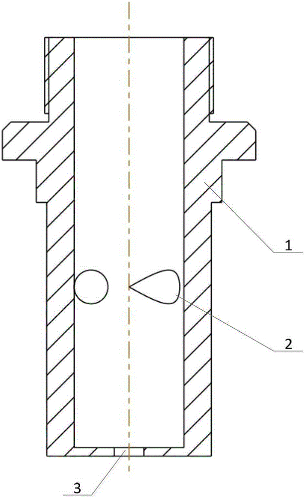
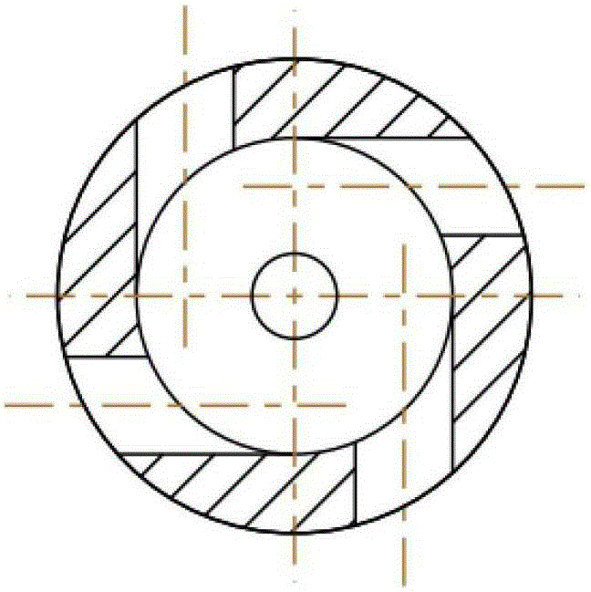
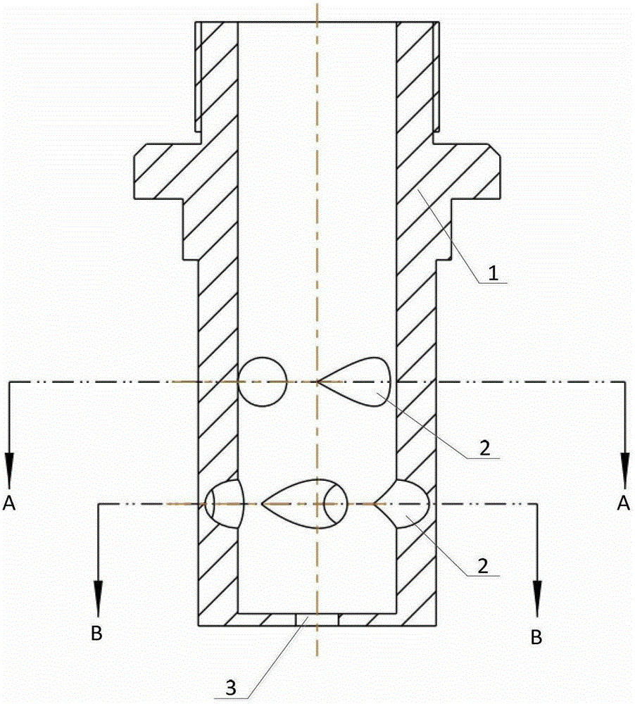
[0017] to combine Figure 1-5 , There is an air swirl hole 2 at the electric nozzle 1 of the plasma igniter. Blow out, create a flame, and ignite the fuel. Among them, the swirl hole 2 is tangent to the inner diameter of the electric nozzle 1, so that the incoming air and the exiting plasma arc produce a swirl effect, enhance the rigidity of the arc, prevent it from being blown obliquely by the external air, ensure the effective diameter of the ignition, and improve the success of the ignition Rate.

[0018] The nozzle 1 of the plasma igniter is provided with a swirl hole 2, the air enters the cavity of the nozzle 1 through the swirl hole 2, and then the plasma arc generated between the nozzle 1 and the cathode is blown out through the outlet channel 3 to form a flame , to ignite the fuel. The swirl hole 2 is tangent to the inner diameter of the electric nozzl...


PUM


Abstract

A purpose of the present invention is to provide a swirling type plasma ignition nozzle, which comprises an electrical nozzle, wherein the electrical nozzle is provided with swirling holes, the bottom of the electrical nozzle is provided with an outlet channel, the swirling hole is tangent to the inner diameter of the electrical nozzle, and the swirling holes are distributed in a single row distribution manner or an upper-lower row distribution manner. According to the present invention, the swirling hole is tangent to the inner diameter of the electrical nozzle, such that it is ensured that air entering the electrical nozzle cavity and the plasma electrical arc on the outlet have swirling effects so as to provide a certain rigidity for the plasma electrical arc, ensure an effective ignition diameter of the plasma electrical arc, prevent tilting due to blowing by external gas, and increase ignition success rate.

Description

technical field [0001] The invention relates to a gas turbine, in particular to an igniter of the gas turbine. Background technique [0002] The performance of the igniter directly affects the working reliability of the gas turbine. The engine is required to be ignited successfully in various complex environments and unpredictable conditions (emergency flameout), that is to say, the combustion chamber inlet pressure is 0.6-1.1MPa, and the fuel inlet temperature can be ignited at -50°C-50°C. At present, the commonly used gas turbine ignition methods include electric spark ignition and semiconductor surface discharge ignition. The spark ignition energy is low and the ignition delay is long. Although the semiconductor surface discharge ignition can obtain a large ignition power, due to the life of the semiconductor, it directly affects the performance and life of the entire ignition device, and the electromagnetic radiation is quite serious. [0003] Plasma ignition is a new ...

Claims


Application Information

Patent Timeline
Patent Type & Authority Patents(China)
IPC IPC(8): F02C7/266
Inventor 潘刚郑洪涛李雅军蔡林杨仁杨洪磊
Owner HARBIN ENG UNIV
Learn More