Hardware lock implementation method and device for multi-core processor

A technology of a multi-core processor and an implementation method, which is applied in the directions of multi-programming devices and resource allocation, etc., can solve the problems of unbalanced absolute delay in accessing hardware locks, reducing the application performance of hardware locks, increasing the time of lock synchronization, etc., and achieving improvement Lock synchronization efficiency, good scalability characteristics, and the effect of opportunity balance

Active Publication Date: 2013-02-20
NAT UNIV OF DEFENSE TECH
View PDF3 Cites 7 Cited by
  • Summary
  • Abstract
  • Description
  • Claims
  • Application Information

AI Technical Summary

Problems solved by technology

Because of the different levels of routers to hardware locks, the delays for each core to access hardware locks are inconsistent, such as Core 2 Relative to Core 0 It needs to go through one more level of routers to access the hardware lock, and the absolute delay of its access must be greater than that of the Core 0 , such a structure leads to an imbalance in the absolute latency of accessing hardware locks between different processor cores
Although the probability of each core issuing lock access on the software is the same, the difference in absolute access delay on the hardware leads to unbalanced lock access. Cores with short absolute access delay (such as Core 0 ) can frequently access locks, while cores with long absolute access delays (such as Core N ) is difficult to acquire locks, and the lock synchronization mechanism can have the highest efficiency only when the number of times each core accesses the lock is balanced, so the above situation will increase the lock synchronization time and reduce the application performance of the hardware lock

Method used


Image

  • Hardware lock implementation method and device for multi-core processor
  • Hardware lock implementation method and device for multi-core processor
  • Hardware lock implementation method and device for multi-core processor

Examples


Embodiment Construction

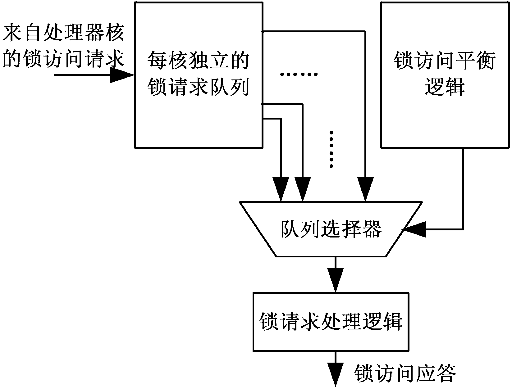
[0040] Such as figure 2 As shown, the implementation steps of the hardware lock implementation method for multi-core processors in this embodiment are as follows:

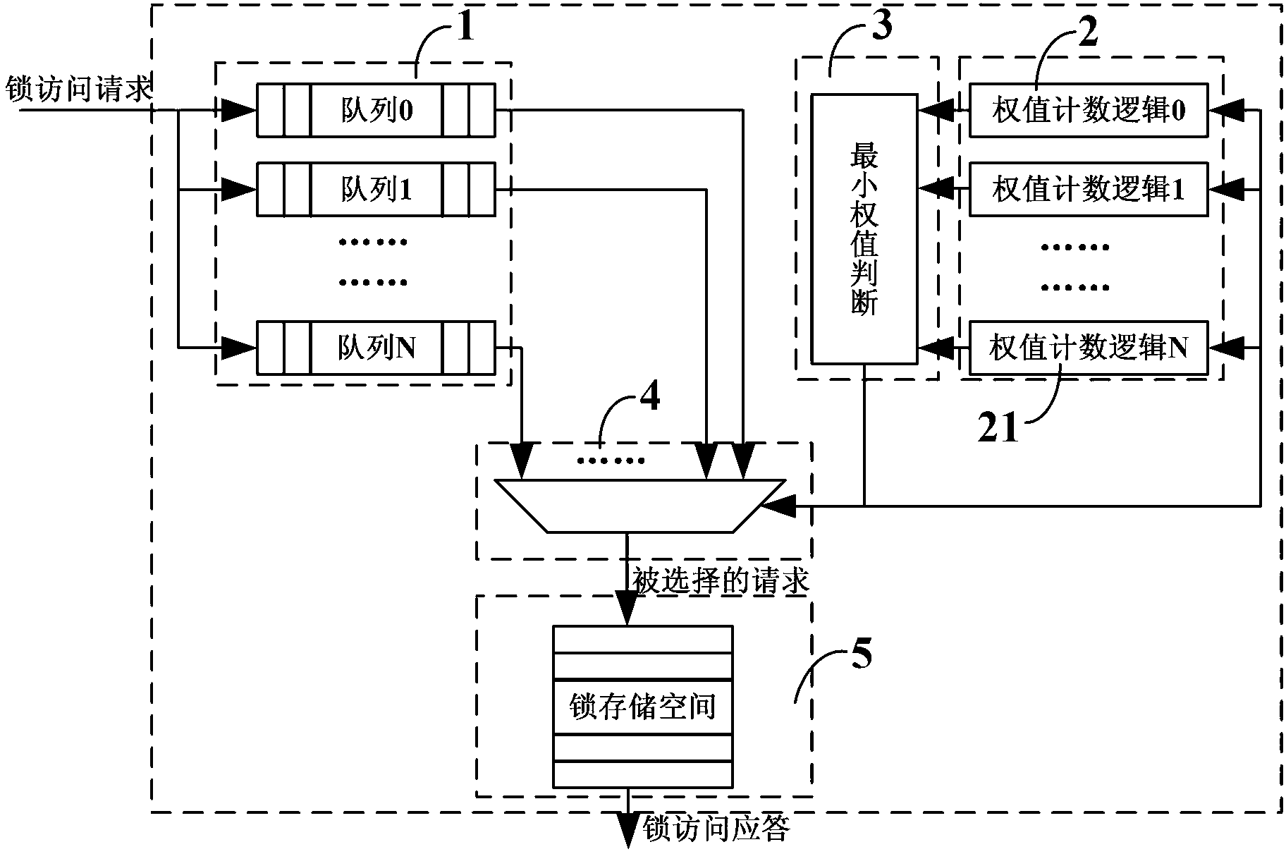
[0041]1) Establish a lock request queue corresponding to the processor core one by one, initialize and set the weight of each lock request queue, and cache the hardware lock access requests sent by each processor core through the lock request queue according to the principle of first-in-first-out;

[0042] 2) Obtain the minimum weight of the lock request queue, select the lock request queue corresponding to the minimum weight to obtain the service, increase the weight of the lock request queue after obtaining the service, and select the first entry from the lock request queue to obtain the service The hardware lock access request executes the lock storage space access operation and returns a response message.

[0043] In this embodiment, the detailed steps for initializing and setting the weights of each lock req...


PUM


Abstract

The invention discloses a hardware lock implementation method and device for a multi-core processor. The method comprises the following steps of: 1) establishing a lock request queue in one-to-one correspondence with a processor core, and initializing and setting the weight of each lock request queue, wherein the lock request queue respectively caches a hardware lock access request sent by each processor core according to the principle of first in first out; and 2) selecting a lock request queue which has the smallest weight and an effective request so as to obtain a service, increasing the weight of the lock request queue progressively after the service is obtained, meanwhile, selecting the first-in hardware lock accesss request from the lock request queue which obtains the service, and carrying out lock storage space access operation, and then returning a response massage. The device comprises a lock request queue unit, a weight counting logic unit, the lowest weight judgement logic, a queue selector and hardware lock storage space access logic. The hardware lock implementation method and device for the multi-core processor has the advantages that each processor core has equalized chance to obtaining the hardware lock, hardware implementation price is low, expanding property is good, the structure simple, and the method is easy to implement.

Description

technical field [0001] The invention relates to the field of multi-core microprocessor design, in particular to a hardware lock implementation method and device for a multi-core processor. Background technique [0002] Lock synchronization is a widely used synchronization method among multiple tasks in software systems, and modern software accesses locks frequently, so improving lock access efficiency is of great benefit to improving software performance. Hardware locks are usually one of the common means of improving lock access efficiency in modern microprocessors. The hardware lock usually has a storage unit integrated in the processor with a certain capacity, which has a fast access speed and is isolated from multi-level storage systems such as Cache, thus avoiding frequent operations such as Cache failure and replacement. Software lock and hardware lock have higher access efficiency. [0003] Storage of the dongle is centralized, at a fixed location within the process...

Claims


Application Information

Patent Timeline
Patent Type & Authority Applications(China)
IPC IPC(8): G06F9/46G06F9/50
Inventor 任巨张明龚锐邓宇石伟郭御风窦强罗莉马爱永王永文
Owner NAT UNIV OF DEFENSE TECH
Why Eureka
Try Eureka