
Bar feeding mechanism

A technology of feeding mechanism and bar, applied in the direction of conveyor objects, transportation and packaging, can solve the problems of high production cost of enterprises, low work efficiency of workers, inconvenient operation of workers, etc., to achieve simple maintenance work, improve work efficiency, Simple structure design

Inactive Publication Date: 2013-02-27
CHONGQING TIANZHIDAO SCI & TECH DEV
View PDF0 Cites 0 Cited by
  • Summary
  • Abstract
  • Description
  • Claims
  • Application Information

AI Technical Summary

Problems solved by technology

[0003] Purpose of the present invention: to solve many problems such as unreasonable structural design of the existing feeding device, which brings inconvenience to workers, low work efficiency of workers, high production cost of enterprises, etc., and proposes a bar feeding mechanism

Method used


Image

  • Bar feeding mechanism

Examples


Embodiment Construction

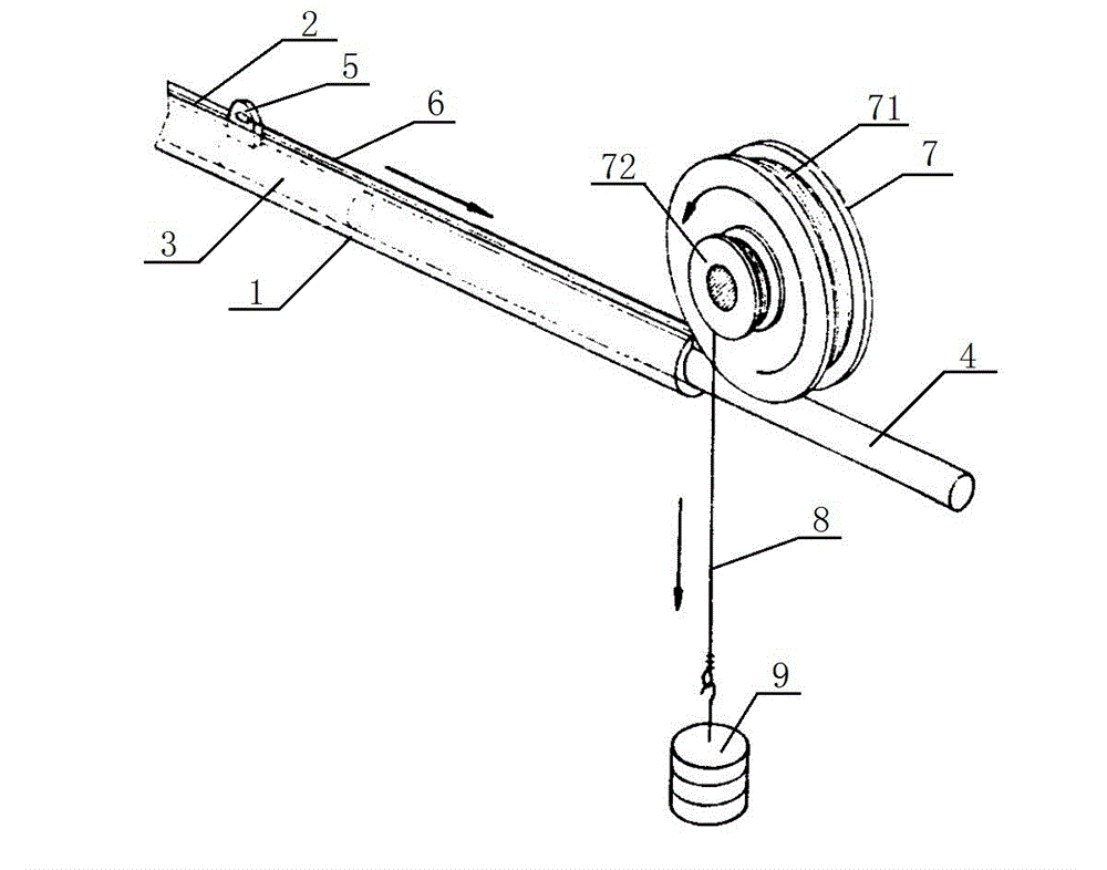
[0010] Such as figure 1 As shown, the present invention provides a kind of rod material feeding mechanism, comprises conduit 1 and duplex sheave 7, and the tube wall of conduit 1 is provided with longitudinal groove 2, and the rod material 4 of front and rear arrangement, pushing Rod 3 and push rod 3 are provided with lug plate 5, and push rod 3 is connected with drag cable 6 through lug plate 5; double sheave 7 is formed by coaxial connection of large sheave 71 and small sheave 72, and drag cable 6 winds Set on the big sheave 71, the small sheave 72 is connected with the weight 9 through the rope 8.

[0011] In this embodiment, the conduit 1 plays a good guiding role for the push rod 3 and the rod 4, the setting of the longitudinal groove 2 provides conditions for the movement of the push rod 3, and the setting of the double sheave 7 makes it possible to pull The cable 6 can be wound around the large sheave 71, thereby pulling the push rod 3 to move forward, thereby sending ...


PUM


Abstract

The invention belongs to the technical field of feeding devices, and particularly relates to a bar feeding mechanism. The bar feeding mechanism comprises a duct and a duplex grooved pulley, wherein a longitudinal groove is formed in the wall of the duct; the duct is internally provided with a bar and a push rod which are arranged with one being in front of the other; the push rod is connected with a stay rope; the duplex grooved pulley is formed by connecting a big grooved pulley and a small grooved pulley in a coaxial way; the stay rope is wound on the big grooved pulley; and the small grooved pulley is connected with a counter weight by a rope. The existing feeding device is not reasonable in structural design, so the manual operation is inconvenient, the working efficiency of workers is low, the production cost of an enterprise is high, etc. The bar feeding mechanism overcomes theses problems of the existing feeding device.

Description

technical field [0001] The invention belongs to the technical field of feeding devices, and in particular relates to a rod feeding mechanism. Background technique [0002] When the workpiece is installed, it is usually necessary to use a feeding device to realize the automatic feeding of the workpiece. At present, the structural design of the feeding device is mostly complicated, and the operation is very troublesome. Not only is it inconvenient for workers to use, but the work efficiency is very low, and the maintenance work in the later period is also very troublesome, which increases the production cost of the enterprise to a certain extent. , It is very unfavorable to the long-term development and progress of the enterprise. Contents of the invention [0003] The purpose of the present invention is to propose a bar feeding mechanism in order to solve many problems such as unreasonable structural design of the existing feeding device, which causes inconvenient operatio...

Claims


Application Information

Patent Timeline
IPC IPC(8): B65G47/74
Inventor 姜静慧
Owner CHONGQING TIANZHIDAO SCI & TECH DEV
Learn More