A spr-based detection system and its detection method

A detection system and area array detector technology, applied in measurement devices, instruments, scientific instruments, etc., can solve the problems of dense arrangement, complex process and high product cost, and achieve the goal of simplifying the process, solving the lattice density and reducing the product cost. Effect

Active Publication Date: 2016-04-06
山东深大光学科技有限公司
View PDF6 Cites 0 Cited by
  • Summary
  • Abstract
  • Description
  • Claims
  • Application Information

AI Technical Summary

Problems solved by technology

[0006] The purpose of the present invention is to provide a detection system based on SPR, aiming to solve the problems of high product cost and complex process caused by the dense arrangement of point light sources in the array light source in the existing SPR-based detection system

Method used


Image

  • A spr-based detection system and its detection method
  • A spr-based detection system and its detection method
  • A spr-based detection system and its detection method

Examples


Embodiment 1

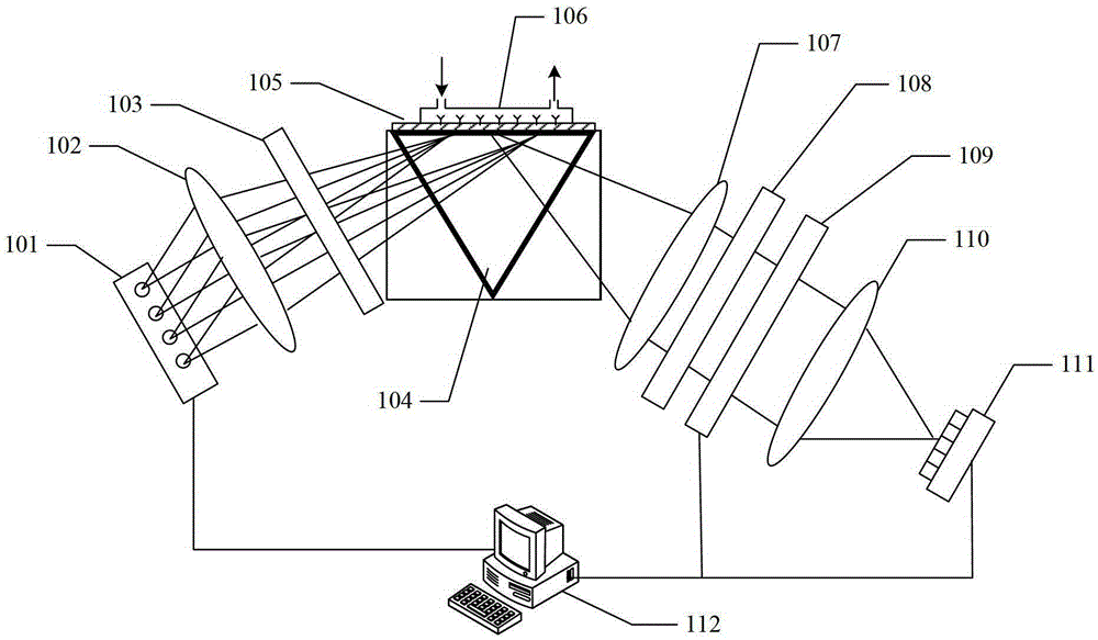
[0028] figure 1 The structure of the SPR-based detection system provided by the first embodiment of the present invention is shown, and for convenience of description, only the parts related to the first embodiment of the present invention are shown.

[0029] In the first embodiment of the present invention, the detection system based on SPR includes: a first area array detector 111; a first array light source 101 arranged by several point light sources for sequentially generating sensing light; a first lens 102, It is used to collimate each sensing light in turn and form outgoing light at different angles. Each point light source is placed on the focal plane of the first lens 102, and combined with the array point light source to perform an electronically controlled angle rough scanning function; the first polarizer 103, for sequentially acquiring polarized light from the sensing light collimated by the first lens 102; the first prism 104, for receiving each polarized light a...

Embodiment 2

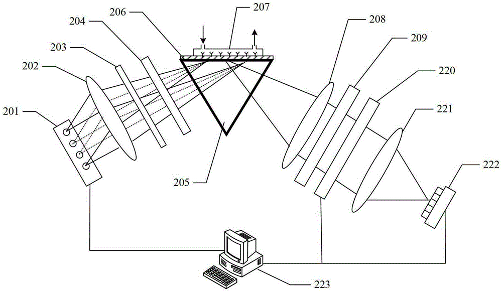
[0033] image 3 The structure of the SPR-based detection system provided by the second embodiment of the present invention is shown, and for the convenience of description, only the parts related to the second embodiment of the present invention are shown.

[0034] In the second embodiment of the present invention, the detection system based on SPR includes: a second area array detector 222; a second array light source 201 arranged by several point light sources for sequentially generating sensing light; a fourth lens 202, It is used to collimate the sensing light sequentially generated by each point light source, and each point light source is placed on the focal plane of the fourth lens 202; Obtain each polarized light in the photosensitive process; the phase modulator 204 is used to sequentially modulate each polarized light obtained by the polarizer 203; the second prism 205 is used to sequentially receive each polarized light modulated by the phase modulator 204, and modu...


PUM


Abstract

The invention belongs to the technical field of photoelectric detections, and provides a detection system and a detection method based on SPR. The system and the method combine a spectrum scanning technique and an angle detection technique or a phase detection technique. Firstly, an SPR resonance angle is obtained by using the angle detection technique or the phase detection technique; a point light source at corresponding position of an array source is lightened while the point light sources at other positions are turned off; then the spectrum scanning technique is used to perform spectrum scanning on the lightened point light source to obtain a spectrum position of an optimum linear area; and the wavelength corresponding to the spectrum position is set as a working wavelength of a spectrum filter. The system and the method realize small-angle and high-precision continuous scanning, make full use of the spectral width of the light source, can prevent dense arrangement of the point light sources in the array source and low utilization of the optical spectrum of the light source, and effectively solve the contradiction between the dense degree of the point light sources in the array source and the scanning angle, thereby reducing product cost and simplifying process.

Description

technical field [0001] The invention belongs to the technical field of photoelectric detection, and in particular relates to an SPR-based detection system and a detection method thereof. Background technique [0002] The surface plasmon resonance (Surface Plasmon Resonance, SPR) phenomenon means that the evanescent wave generated when the incident light is totally reflected at the glass interface excites the free electrons on the metal surface to form a surface plasmon and generate a plasma wave. Under certain conditions, the evanescent wave The wave resonates with the plasma wave, and the energy of the incident light is coupled into the surface plasmon, which makes the energy of the reflected light attenuate significantly. This phenomenon is applied in the fields of biology, medicine, and chemistry. It is mainly used to detect the interaction between biomacromolecules, obtain the bonding information of each step between the reactant molecules, and determine the kinetic cons...

Claims


Application Information

Patent Timeline
Patent Type & Authority Patents(China)
IPC IPC(8): G01N21/552
Inventor 邵永红顾大勇
Owner 山东深大光学科技有限公司
Why Eureka
Try Eureka