
Arc-control device of breaker

An arc extinguishing device and circuit breaker technology, applied in high-voltage air circuit breakers, circuits, electrical components, etc., can solve the problems of short arc process, easy formation of air bubbles, unfavorable arc breaking, etc., and achieve the reduction of operating power and size. Effect

Active Publication Date: 2013-02-27
CHINA XD ELECTRIC CO LTD +1
View PDF3 Cites 12 Cited by
  • Summary
  • Abstract
  • Description
  • Claims
  • Application Information

AI Technical Summary

Problems solved by technology

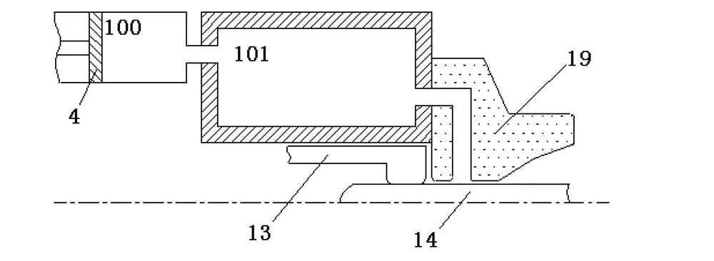
Furthermore, the existing arc extinguishing device uses a single expansion chamber. Since the arc process is extremely short (about 20 milliseconds), it is difficult to mix the hot and cold gases in the expansion chamber evenly in such a short time, so that the conductive particles are blown away. In the air flow, because of the uneven mixing of hot and cold gases, it is easy to form bubbles, which is not conducive to the interruption of the arc
[0003] On the other hand, no matter what kind of electric current is broken in the existing structure, the compressed air cylinder 100 is compressed, such as figure 1 As shown, but the actual situation is that when breaking a small current, compressed gas is needed to build up the pressure in the expansion chamber, while breaking a large current is mainly to use the arc's own ability to build up pressure in the expansion chamber (no compressed gas or only less Therefore, the compressed air of the existing arc extinguishing device combined with self-energy cannot adapt to the size of the breaking current and make corresponding adjustments, that is, the arc extinguishing device may be compressed when the compressed air is not needed, thus causing waste of work

Method used


Image

  • Arc-control device of breaker
  • Arc-control device of breaker
  • Arc-control device of breaker

Examples


Embodiment Construction

[0025] The technical scheme of the present invention will be described in detail below in conjunction with the accompanying drawings.

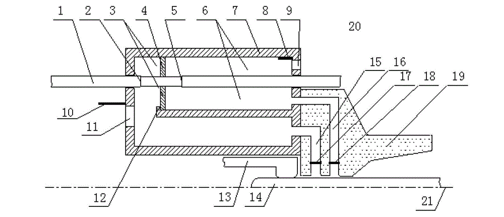
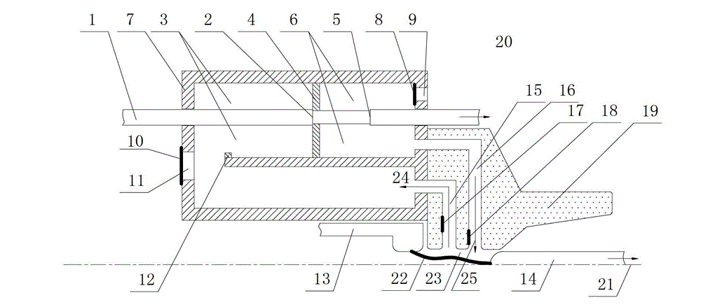
[0026] see Figure 2 to Figure 7As shown, a circuit breaker arc extinguishing device of the present invention is symmetrically arranged along the axis 21, and consists of a piston rod 1, a piston 4, a cylinder 7, a first check valve 8, a first air hole 9, a second check valve 10, The second air hole 11, the limit block 12, the stationary contact 13, the moving contact 14, the first air channel 15, the second air channel 16, the third one-way valve 17, the fourth one-way valve 18, and the spout 19 are composed. The periphery 20 of the arc extinguishing device is filled with an arc extinguishing medium gas (such as sulfur hexafluoride gas, air, etc.). The piston rod 1 passes through the cylinder 7; the piston rod 1 has two limiting surfaces, the first limiting surface 2 and the second limiting surface 5, and the piston 4 is sleeved on the outer...


PUM


Abstract

The invention discloses an arc-control device of a breaker, which comprises a piston rod, a piston, an air cylinder, a static contact, a moving contact and a nozzle, wherein the air cylinder is isolated by the piston to form a hot air chamber and a cold air chamber, the piston is sleeved at the periphery of the piston rod and is positioned between a first limiting surface and a second limiting surface of the piston rod, and the nozzle is provided with a first air channel and a second air channel which are respectively communicated with the hot air chamber and the cold air chamber. According to the invention, hot airflow of arc heating can enter the hot air chamber, and in arc blowout, the cold airflow in the cold chamber can blow away conductive particles, so that the phenomenon that in the traditional structure, the cutting-off is not successful due to heat breakdown and air bubbles of the airflow can be avoided; the mode of forming the pressure by pressure air of the piston and the mode of forming the pressure by arc heating expansion are integrated, so that the size of the arc-control device is reduced; through the limiting surfaces of the piston rod, the drive mode of the piston can automatically adapt to the magnitude of current; and the expansion pressure generated by arc drives the direction of the movement of the piston to be constant with the direction of the movement of the piston rod, so that the work of the breaker can be reduced.

Description

technical field [0001] The invention belongs to the field of high-voltage switches, in particular to an arc extinguishing device for a circuit breaker. Background technique [0002] At present, circuit breakers mainly adopt self-energy or arc extinguishing devices combining compressed air and self-energy, and most of the existing arc extinguishing devices use a single expansion chamber 101, such as figure 1 shown. When the current is broken, the energy of the arc current generates heat, which increases the air pressure in the expansion chamber 101. When the current crosses zero, the arc energy disappears for a short time, and the hot gas in the expansion chamber is ejected out of the nozzle 19, and is taken away to form an arc. Conductive particles, so as to achieve current breaking. Although the hot air flow can be used to blow away the conductive particles to achieve breaking, because the hot air flow is not conducive to the reduction of the temperature of the arc area, ...

Claims


Application Information

Patent Timeline
IPC IPC(8): H01H33/91
Inventor 朱琦琦程立吕军玲徐刚马冲
Owner CHINA XD ELECTRIC CO LTD
Learn More