Video Coding

A coding and encoder technology, applied in television, digital video signal modification, pulse modulation TV signal transmission, etc.

Inactive Publication Date: 2013-02-27
SKYPE
View PDF4 Cites 13 Cited by
  • Summary
  • Abstract
  • Description
  • Claims
  • Application Information

AI Technical Summary

Problems solved by technology

However, at the same time the rate term R will increase, and at some point related to λ, the increase in R will outweigh the decrease in D

Method used


Image

  • Video Coding
  • Video Coding
  • Video Coding

Examples


Embodiment Construction

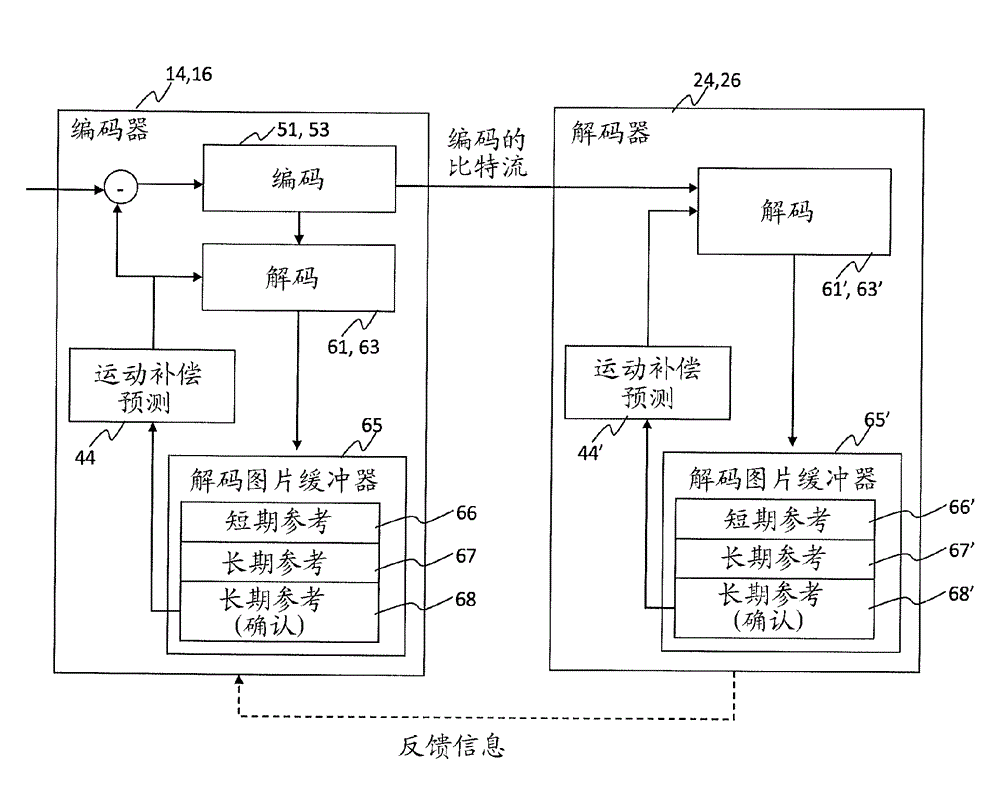
[0080] The following describes coding systems and methods that utilize information fed back from the decoder to the encoder, such as packet and / or frame arrival status, in order to further adapt the loss-adaptive rate-distortion optimization process and thereby improve overall rate-distortion performance. Encoder is similar to about image 3 Encoder as described but with a modified mode selection module 49. It can be used to encode video streams of the kind illustrated in Figure 1 and implemented in applications such as figure 2 in the communication system.

[0081] As mentioned, mode selection can involve optimizing (e.g. minimizing) a Lagrange-type function:

[0082]

[0083] where J denotes a Lagrangian function, D denotes a measure of distortion (a function of mode o and macroblock m or macroblock subpartition), R is the bit rate, and λ is a parameter defining the tradeoff between distortion and rate.

[0084] In the conventional case the distortion term D only take...


PUM


Abstract

A method of performing a rate-distortion optimization process comprising, for each of a plurality of target image portions to be encoded in each of a plurality of frames, selecting a preferred one of a set of encoding modes by optimizing a function comprising an estimate of distortion for the target image portion and a measure of bit rate required to encode the target image portion, wherein the estimate of distortion is based on source coding distortion and an estimate of a distortion that would be experienced due to possible loss over the channel; encoding the target image portion into the encoded video stream using the selected encoding mode; and transmitting the encoded video stream over the channel. The rate-distortion optimization process for a current one of the frames is performed in dependence on feedback received from the receiving terminal based on an earlier one of the frames.

Description

technical field [0001] The invention relates to balancing the tradeoff between bit rate and distortion when selecting an encoding mode for encoding a portion of a video signal. The invention may be particularly (but not exclusively) applicable when encoding video streams in real-time, i.e. live video streams such as those of a video call, where the encoder must be dynamic when and as the stream is received from a camera or the like encode the stream for sending. Background technique [0002] exist Figure 1a The video data stream to be encoded is schematically illustrated in . The stream comprises a number of frames (F), each representing a video image at a different respective instant. As will be familiar to those skilled in the art, for encoding purposes, each frame (F) is divided into sections and each section may also be subdivided into smaller sub-sections, each section or sub-section comprising a plurality of pixels. For example, according to one term, each frame of...

Claims


Application Information

Patent Timeline
Patent Type & Authority Applications(China)
IPC IPC(8): H04N7/26H04N7/50
CPCH04N19/00278H04N7/367H04N19/00242H04N19/00727H04N7/26244H04N19/0003H04N7/5086H04N7/26154H04N19/00351H04N19/00933H04N7/26308H04N7/26031H04N7/26234H04N19/00175H04N7/64H04N19/58H04N19/107H04N19/147H04N19/166H04N19/176H04N19/19H04N19/89
Inventor D.赵M.尼尔森R.瓦芬A.杰弗里莫夫S.V.安德森P.卡尔森
Owner SKYPE
Why Eureka
Try Eureka