Welding wire feeder with magnetic rotational speed sensor

A magnetic sensor and wire feeder technology, applied in the field of gears driven by motors in the U.S. Provisional No. 61/355,815 filed on the 7th, can solve the problems of reducing the efficiency of optical tachometers, malfunctioning of optical tachometers, and blocking LED light paths, etc.

Inactive Publication Date: 2013-02-27
ILLINOIS TOOL WORKS INC
View PDF9 Cites 9 Cited by
  • Summary
  • Abstract
  • Description
  • Claims
  • Application Information

AI Technical Summary

Problems solved by technology

However, optical tachometers (which can be mounted on the electric shaft of the wire feed motor) are prone to failure in high temperature environments
Additionally, dust or contaminants in the welding environment may block the light path of the LEDs, further reducing the efficiency of the optical tachometer
Additionally, optical tachometers provide close connection to the motor drive of the wire feeder, which improves resolution but also increases the difficulty of removing or replacing the motor

Method used


Image

  • Welding wire feeder with magnetic rotational speed sensor
  • Welding wire feeder with magnetic rotational speed sensor
  • Welding wire feeder with magnetic rotational speed sensor

Examples


Embodiment Construction

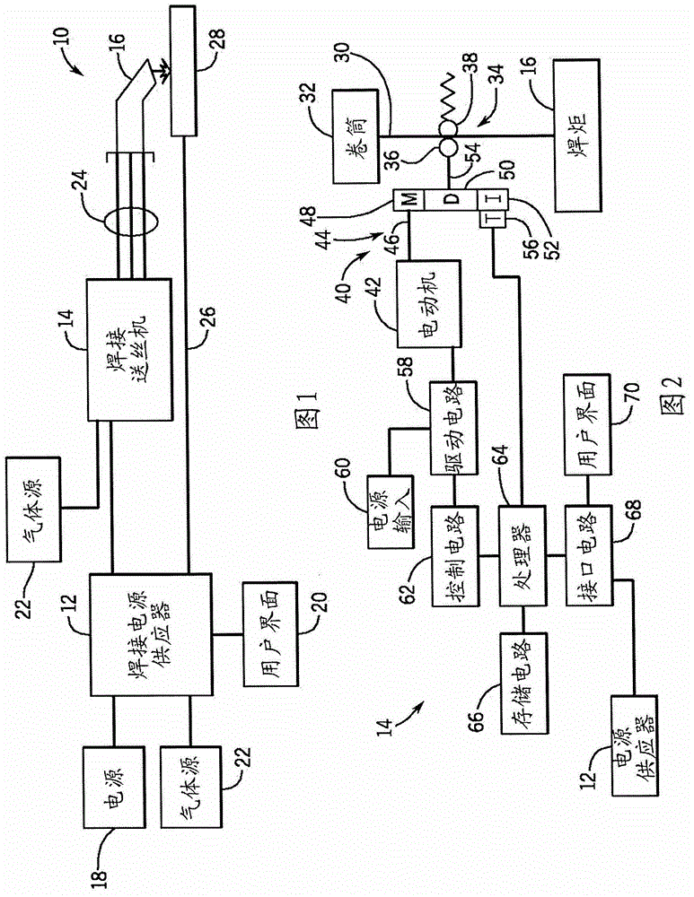
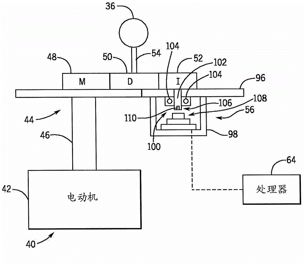
[0015] The present invention presents an exemplary embodiment of a welding wire feeder provided with a magnetic wire feed speed sensor. The welding wire feeder includes an electric motor configured to drive a drive roller to deliver welding wire to a welding torch. This motor also drives the idler gear, and the magnetic wire feed speed sensor measures the rotational speed of the idler gear by calculating its angular position and angular velocity. The rotational speed of another gear or rotating part of the system can be measured in a similar way. Specifically, in the described embodiment, angular position and angular velocity are measured with magnets located on a shaft connected to an idler gear and above an integrated circuit that responds to the shaft at regular intervals. The angular position is sampled. This angular position data can then be used to determine the angular velocity of the idler gear, which can be further converted into a wire feed speed measurement.

[0...


PUM


Abstract

A welding wire feeder (14) includes a magnetic rotational sensor system (56) configured to measure a parameter indicative of a wire feed speed of the welding wire feeder. The magnetic rotational sensor system includes a dipole magnet (110) coupled to a gear (52) driven by an electric motor (42) of the welding wire feeder and a magnetic sensor (108) disposed adjacent to the dipole magnet and configured to measure an angular position of the dipole magnet. The magnetic rotational sensor system also includes a processor (64) configured to receive signals of the angular position measured by the magnetic sensor and to calculate a wire feed speed of the welding wire feeder based upon the angular position signals and configuration parameters of the welding wire feeder.

Description

[0001] Cross reference to related applications [0002] This application asserts U.S. Patent Application No. 13 / 158,005, "Welding Wire Feeder with Magnetic Speed ​​Sensor," filed June 10, 2011, and U.S. Provisional Patent Application No. 61 / 355,815, filed June 17, 2010 Priority to Magnetic Speed ​​Sensor for Welding Wire Feeder, the above application is hereby incorporated by reference. Background technique [0003] The present invention relates generally to welding systems, and more particularly to welding wire feeders provided with magnetic rotational speed sensors. [0004] The welding process has become an increasingly ubiquitous process in a variety of industries and applications. Welding operations rely on various types of equipment to ensure that the correct amount of welding material (eg, wire feed, shielding gas, etc.) is supplied to the weld for the required time. For example, metal inert gas (MIG) shielded welding typically relies on a wire feeder to ensure that t...

Claims


Application Information

Patent Timeline
Patent Type & Authority Applications(China)
IPC IPC(8): B23K9/133
CPCB23K9/125B23K9/1336B23K9/133B23K9/12
Inventor 布赖恩·李·奥特杰里米·丹尼尔·奥费雷施
Owner ILLINOIS TOOL WORKS INC
Why Eureka
Try Eureka