Laminate structure with embedded cavities and related method of manufacture

A form, integrated layer technology, applied in the direction of lamination, lamination device, lamination auxiliary operation, etc., can solve the problems of expensive, insufficient performance, complex and so on

Active Publication Date: 2013-02-27
NITTO DENKO CORP
View PDF4 Cites 17 Cited by
  • Summary
  • Abstract
  • Description
  • Claims
  • Application Information

AI Technical Summary

Problems solved by technology

However, even these and other existing solutions have been too restrictive, underperforming, complex and expensive due to the wide range of industrial scale use

Method used


Image

  • Laminate structure with embedded cavities and related method of manufacture
  • Laminate structure with embedded cavities and related method of manufacture
  • Laminate structure with embedded cavities and related method of manufacture

Examples


Embodiment Construction

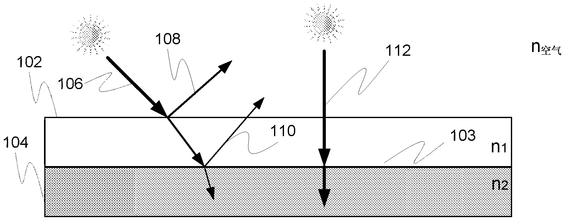
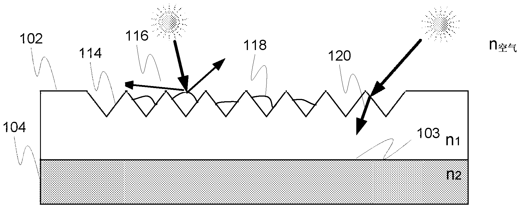
[0067] Figures 1a and 1b have already been introduced in conjunction with the description of the background art.

[0068] The principles of the invention can be employed in a variety of use cases and scenarios. For example, the scenario may involve the use of visible light, infrared light and / or ultraviolet light.

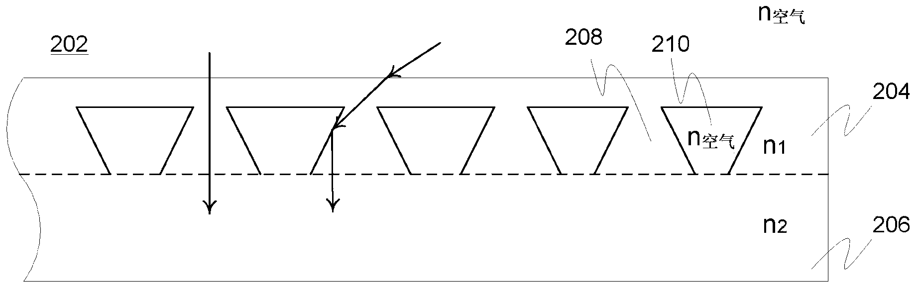
[0069] In some embodiments of the invention, laminated structures may be made from large elements such as large panels or membranes. These elements may be provided with optical patterns that have a desired optical function, such as a coupling (eg incoupling or outcoupling) function. Patterns with smaller surface relief forms may be used, eg grating, binary, flared, oblique and / or trapezoidal forms. Essentially any of a discontinuous pattern (eg, raster pixels, small recesses) or a continuous form, elongated recesses or channels, two-dimensional or three-dimensional may be used. It is preferred to have at least a small flat part, ie contact surface, on the laminati...


PUM


Abstract

An integrated laminate structure (202, 302, 402, 502, 602, 702a, 702b, 801, 902, 1002, 1216) adapted for application in the context of solar technology, wafer technology, cooling channels, greenhouse illumination, window illumination, street lighting, traffic lighting, traffic reflectors or security films, comprising a first carrier element (206, 304, 406, 505, 506, 606, 704, 804, 1006, 1204) such as a piece of plastic or glass, optionally comprising optically substantially transparent material enabling light transmission therethrough, a second carrier element (204, 306, 404, 504, 505, 604, 702, 802, 1004, 1206) provided with at least one surface relief pattern (308, 802a, 1206b) comprising a number of surface relief forms (208, 308a, 308b, 408, 412, 508, 510, 608, 610, 708) and having at least one predetermined optical function (708a, 710, 712) relative to incident light, said second carrier element optionally comprising optically substantially transparent material enabling light transmission therethrough, the first and second carrier elements being laminated together such that the at least one surface relief pattern has been embedded within the established laminate structure and a number of related cavities (210, 308b, 408, 410, 412, 508, 510, 608, 610, 709) have been formed at the interface of said first and second carrier elements. An applicable method of manufacture is presented.

Description

technical field [0001] In general, most embodiments of the invention relate to optics. In particular, but not exclusively, the invention relates to laminated structures with embedded optically functional cavities and methods for their manufacture. Background technique [0002] Traditionally, microstructures have been fabricated exclusively on the surface area of ​​optically transparent substrates, eg microprisms or gratings containing different optical devices such as lighting and electronics. These structures are initially configured to (re)orient, couple, or interact with incident light in some predetermined way, but positioning these structures on the surface of a material often poses at least long-term, if not immediate, problems and disadvantages. [0003] That is, naturally depending on the situation of use, surface relief structures in the optical sense, such as coupling optics, are often subject to stresses caused by various external factors such as contamination, u...

Claims


Application Information

Patent Timeline
Patent Type & Authority Applications(China)
IPC IPC(8): B32B33/00H01L31/048H01L31/0236H01L31/0232H01L33/48
CPCB32B37/12B32B38/145B32B37/00B32B38/06Y02E10/52H01L31/0522B32B37/24F21V5/00H01L31/048B32B37/142B29D11/0073H01L31/0547H01L31/0543B29D11/00788B29D11/00346H01L31/0236Y10T156/1039Y10T156/10Y10T428/24562Y10T428/24364G02B6/10G02B6/42B32B17/06
Inventor 卡里·林科
Owner NITTO DENKO CORP
Why Eureka
Try Eureka