Changing device for engine break-in test and clamping mechanism for exhaust tube of changing device for engine break-in test

A technology of clamping mechanism and exhaust pipe, which is applied to hand-held tools, manufacturing tools, etc., can solve the problems of complex connection structure, large labor intensity and working time of workers, and reduce the test efficiency of engine running-in test, so as to improve the installation efficiency. Effect

Active Publication Date: 2013-03-06
CAMALUOYANGELECTROMECHANIC
View PDF11 Cites 4 Cited by
  • Summary
  • Abstract
  • Description
  • Claims
  • Application Information

AI Technical Summary

Problems solved by technology

During the running-in test of the engine, it is necessary to be equipped with different types of flanges to connect with the exhaust pipe, and the connection structure between the existing exhaust pipe and the exhaust port of the engine is relatively complicated. For its specific structure, see a " Engine automation test overall bench", including the smoke exhaust device, the smoke exhaust device is composed of smoke exhaust seat, slide, exhaust pipe, handle, spring and connecting rod, the slide sleeve is set in the exhaust pipe, and the exhaust pipe is composed of exhaust pipe Supported by the smoke holder, the handle is connected to the sliding cylinder through the connecting rod, one end of the spring is connected to the exhaust pipe, and the other end is connected to the handle. The smoke exhaust device is connected to the exhaust port of the engine during the engine inspection process to detect various performances of the engine. , the handle, connecting rod and slider can realize the accurate docking with the exhaust port of the engine
The connection structure connecting the engine smoke outlet and the exhaust pipe is relatively complicated, and each connection process between the engine and the corresponding exhaust pipe will consume a lot of labor intensity and working time for the workers, which reduces the test of the engine running-in test. efficiency

Method used


Image

  • Changing device for engine break-in test and clamping mechanism for exhaust tube of changing device for engine break-in test
  • Changing device for engine break-in test and clamping mechanism for exhaust tube of changing device for engine break-in test
  • Changing device for engine break-in test and clamping mechanism for exhaust tube of changing device for engine break-in test

Examples


Embodiment Construction

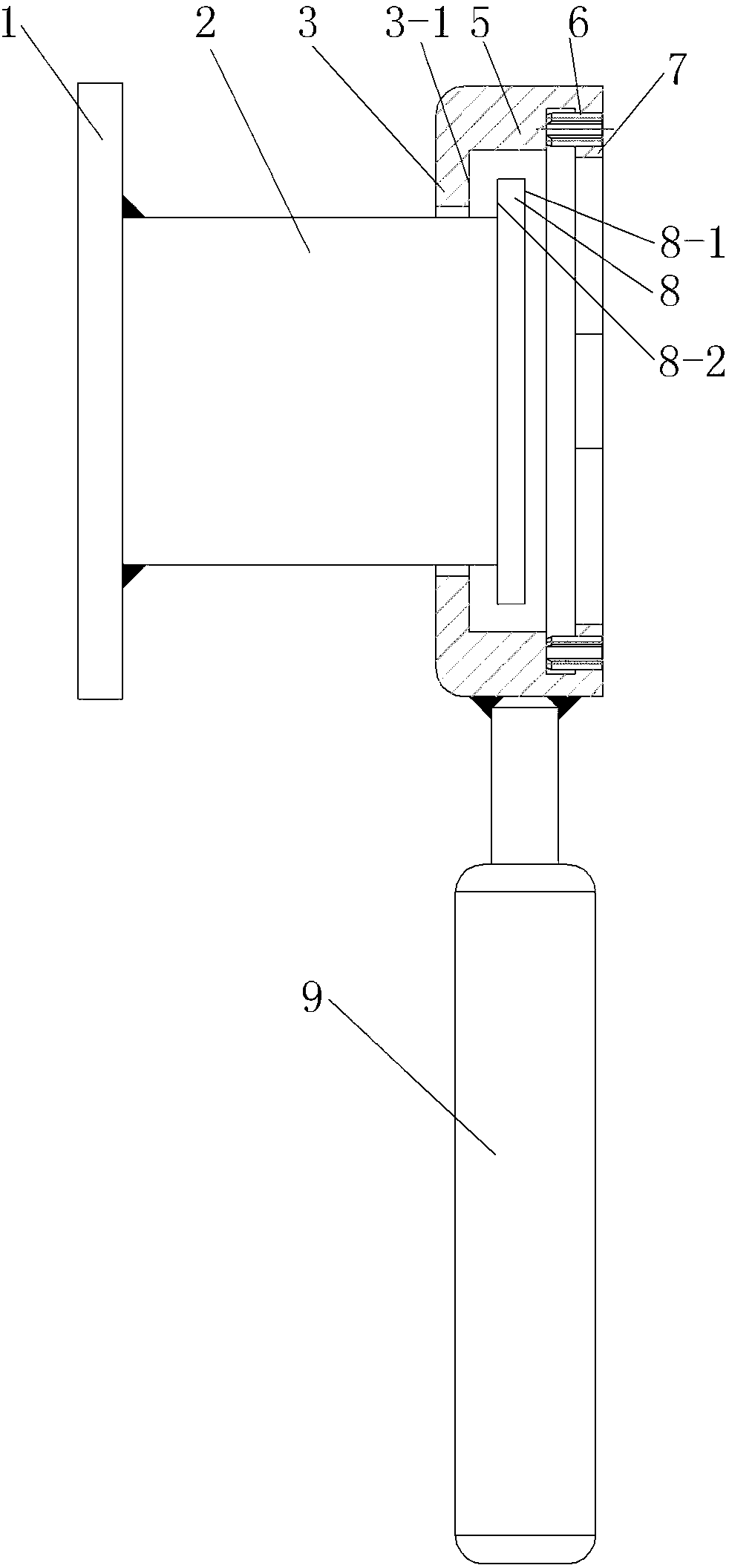
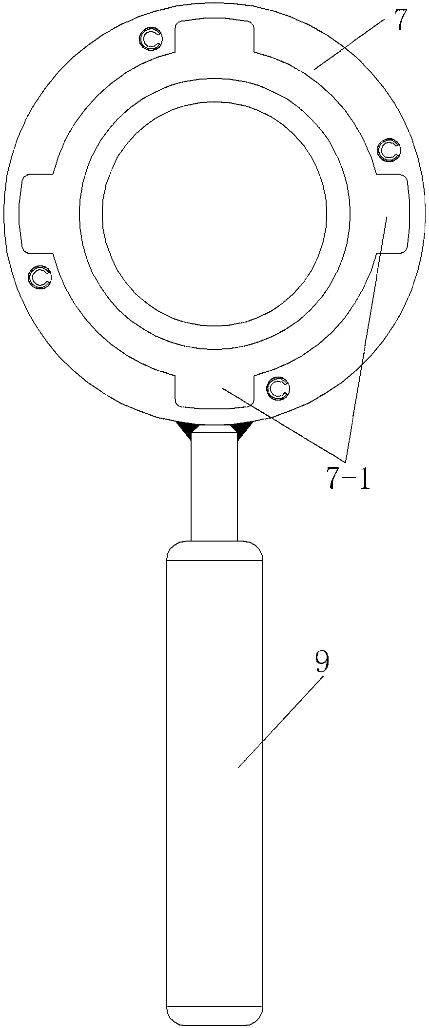
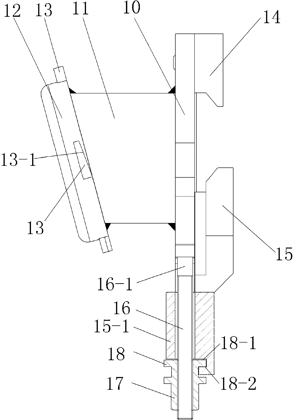
[0029] Examples of replacement devices for engine break-in tests are Figure 1~11Shown: including the clamping mechanism for the exhaust pipe and the disassembly mechanism for disassembling the clamping mechanism. Wherein the clamping mechanism includes a connecting body, and the connecting body includes a connecting plate 10 and a clamping mechanism pipe 11 arranged at the lower end of the connecting plate 10, and the connecting plate 10 is provided with an inner hole of the clamping mechanism pipe 11 and a discharge pipe of a corresponding exhaust pipe. Connecting holes for gas channels to communicate with each other. The upper end of the connecting plate 10 is provided with a movable jaw 15 and a fixed jaw 14 arranged forward and backward along the radial direction of the connecting hole, and the connecting plate 10 is provided with an installation groove 10-1 whose groove depth extends along the front-to-back direction, wherein the installation groove 10-1 The middle wall...


PUM


Abstract

The invention relates to a changing device for engine break-in test and a clamping mechanism for an exhaust tube of the changing device for engine break in test. The clamping mechanism for the exhaust tube comprises a connection body, wherein a connection hole which vertically extends along the axial direction is formed in the connection body, a movable jaw and a fixed jaw which are distributed back and forth along the radial direction of the connection hole are arranged on the upper end of the connection body, the clamping mechanism further comprises a drive part which drives the movable jaw to move towards the fixed jaw along the longitudinal direction and is locked in place, grooves with opposite notches are respectively formed on the movable jaw and the fixed jaw, a connection body limiting surface which has an upward limiting direction and is limitedly matched with a lower end face of a corresponding exhaust tube flange, and the grooves respectively have a groove wall which is used for being in jack matching with the shoulder part of the upper end of the corresponding exhaust tube flange so as to commonly act with the connection body limiting surface to clamp and fix the corresponding exhaust tube flange. The provided clamping mechanism for the exhaust tube is simple in structure, is convenient to operate, and is used for quickly clamping the exhaust tube.

Description

technical field [0001] The invention relates to a replacement device for an engine running-in test and a clamping mechanism for an exhaust pipe thereof. Background technique [0002] After the engine is assembled, a running-in test is usually carried out so that it can withstand the proper load, reduce the amount of wear in the initial stage, prolong the service life of the engine, check and eliminate defects in the assembly, and make the engine parts Obtain a good fit in order to obtain good dynamic performance and mechanical performance. During the running-in test of the engine, it is necessary to be equipped with different types of flanges to connect with the exhaust pipe, and the connection structure between the existing exhaust pipe and the exhaust port of the engine is relatively complicated. For its specific structure, see a " Engine automation test overall bench", including the smoke exhaust device, the smoke exhaust device is composed of smoke exhaust seat, slide, ...

Claims


Application Information

Patent Timeline
IPC IPC(8): B25B27/14
Inventor 李小亮孙丽薛鹏余赵小平任春燕程军张宏敏卢杉郭斌
Owner CAMALUOYANGELECTROMECHANIC
Why Eureka
Try Eureka