In-mold rubber mouth shearing mechanism

A glue mouth and mold technology, which is applied in the field of in-mold glue mouth cutting mechanism, can solve the problems of wasting manpower and equipment, and the cutting place is not beautiful enough, so as to achieve the effect of beautiful cutting place, saving manpower and equipment cost

Active Publication Date: 2016-12-21
SUZHOU MITAC PRECISION TECH
View PDF5 Cites 0 Cited by
  • Summary
  • Abstract
  • Description
  • Claims
  • Application Information

AI Technical Summary

Problems solved by technology

[0004] In order to solve the above problems, the purpose of the present invention is to provide an in-mold rubber mouth cutting mechanism to overcome the defects in the prior art that follow-up labor or jigs are required to cut the glue mouth, waste of manpower and equipment, and the cutting place is not beautiful enough. insufficient

Method used


Image

  • In-mold rubber mouth shearing mechanism
  • In-mold rubber mouth shearing mechanism
  • In-mold rubber mouth shearing mechanism

Examples


Embodiment Construction

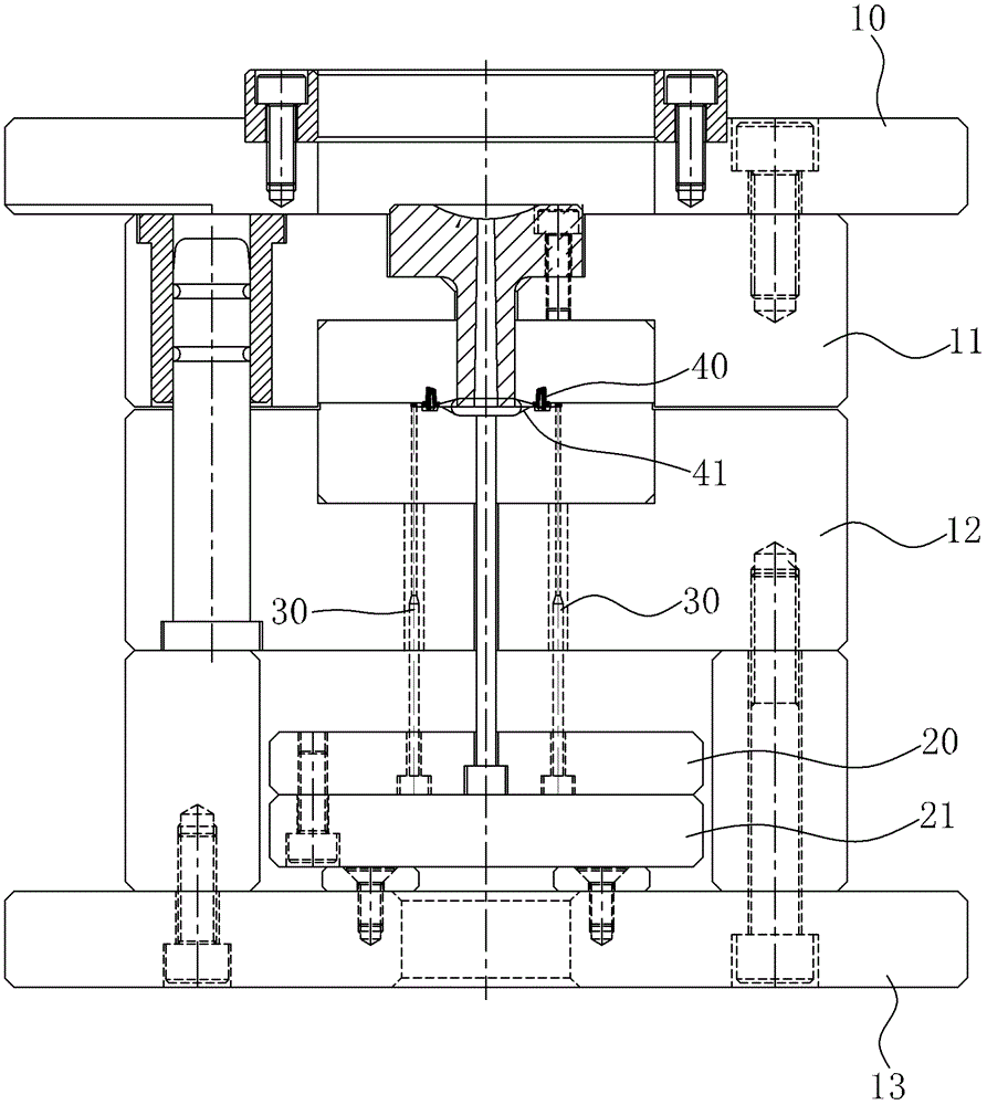
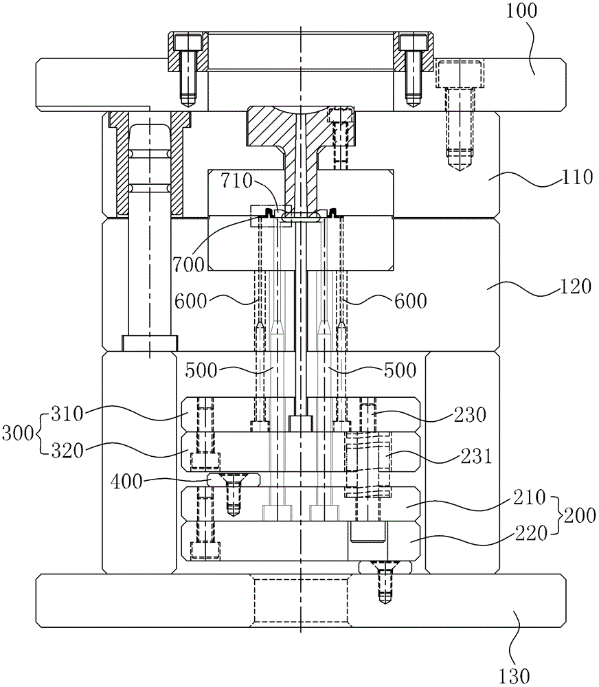
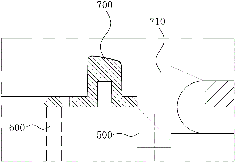
[0022] see figure 2 , image 3 and Figure 4 As shown, the in-mold rubber mouth shearing mechanism of the present invention is applied in a mould. The rubber mouth cutting mechanism includes:

[0023] The first ejector plate 200, which is located above the lower fixing plate 130, the first ejector plate 200 includes a first upper ejector plate 210 and a first lower ejector plate 220;

[0024] The second ejector plate 300 is located above the first ejector plate 200 above. The second ejector plate 300 includes a second upper ejector plate 310 and a second lower ejector plate 320. The lower fixed plate 130 is provided with There is a support column 131 to support the second ejector plate 300, the first ejector plate 200 and the second ejector plate 300 are connected by a contour screw 230, and a first elastic element 231 is arranged outside the contour screw 230, In this embodiment, the first elastic element 231 is a spring;

[0025] Limiting block 400, which is arranged o...


PUM


Abstract

The invention relates to an in-mold gate shearing mechanism applied in a mold. The in-mold gate shearing mechanism includes: a first ejector plate, which is disposed over a lower fixation plate of the mold and is composed of a first upper ejector plate and a first lower ejector plate; a second ejector plate, which is disposed over the first ejector plate and consists of a second upper ejector plate and a second lower ejector plate; a stop block, which is arranged on the first ejector plate and moves together with the first ejector plate when the first ejector plate is ejected, the limiting block and the movement, with clearance disposed between the stop block and the second ejector plate; gate ejector pins, one ends of which are arranged in the first ejector plate and the other ends of which contact the gate; product ejector pins, one ends of which are disposed in the second ejector plate and the other ends of which contact the product. The in-mold gate shearing mechanism provided in the invention needs no shearing action after the product is ejected, thus saving labor and equipment cost. And the shearing part between the product and the gate is beautiful.

Description

【Technical field】 [0001] The invention relates to a mold mechanism, in particular to an in-mold rubber mouth cutting mechanism. 【Background technique】 [0002] In the plastic mold manufacturing industry, there are more and more plastic products for appearance parts. The requirements for this kind of appearance parts are very strict. Manufacturing puts forward higher requirements. [0003] After the product is injection molded in the mold production, there are still glue holes on the product, please refer to figure 1 , which is a schematic diagram of a mold mechanism in the prior art. This existing mold mechanism comprises: upper fixed plate 10, female template 11, male template 12, lower fixed plate 13 and upper ejector plate 20, lower ejector plate 21, product thimble 30, product 40 is taken out after molding is completed, due to glue There is no in-mold cutting mechanism at the mouth 41, the product is ejected together with the glue mouth, and the glue mouth 41 is still...

Claims


Application Information

Patent Timeline
Patent Type & Authority Patents(China)
IPC IPC(8): B29C45/38
Inventor 郭雷
Owner SUZHOU MITAC PRECISION TECH
Why Eureka
Try Eureka