The central automatic switch reversing device in the slide sorter

A technology of reversing device and sorting machine, which is applied to conveyor objects, transportation and packaging, etc., can solve the problems that the equipment cannot meet the set function, affect the noise index of the equipment, reduce the service life of parts, etc., so as to reduce the actual use cost. And the effect of maintenance cost, service life and reliability improvement, and reduction of installation difficulty

Active Publication Date: 2016-02-17
SHANGHAI DAMON LOGISTICS TECH
View PDF7 Cites 1 Cited by
  • Summary
  • Abstract
  • Description
  • Claims
  • Application Information

AI Technical Summary

Problems solved by technology

[0006] 1. When the traveling roller contacts the board one, due to the high running speed of the traveling roller, a large impact force will be generated when the two contact in an instant, and the service life of the parts will be seriously reduced after long-term use
[0007] 2. Because the impact force generated by the momentary contact between the walking roller and the board is very large, the impact noise generated in the moment is also relatively large
Affect the overall noise index of the equipment
[0008] 3. From figure 1 , figure 2 It can be seen that there is a shock absorbing pad 6 on both sides of the board 2, the purpose is to reduce the noise generated by the impact when the board 2 rotates to the limit position. With this design, the noise is indeed reduced, but the shock absorbing pads are all elastic Material, when the board 2 touches the shock absorbing pad, the board 2 will be ejected a certain distance by the reaction force of the shock absorbing pad 6, which will cause the contact between the board 2 and the walking roller 7, posing a safety hazard
[0009] 4. Plate 1, plate 2 and the shock absorber are all separate parts, and they are positioned separately during installation, which leads to cumulative errors during the installation process, and ultimately causes the equipment to fail to meet the set function after installation

Method used


Image

  • The central automatic switch reversing device in the slide sorter
  • The central automatic switch reversing device in the slide sorter
  • The central automatic switch reversing device in the slide sorter

Examples


Embodiment Construction

[0031] The present invention will be further described below in conjunction with specific examples.

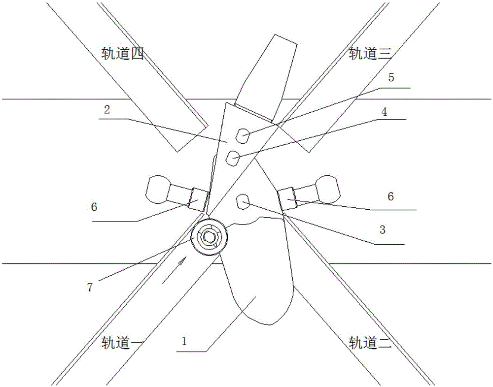
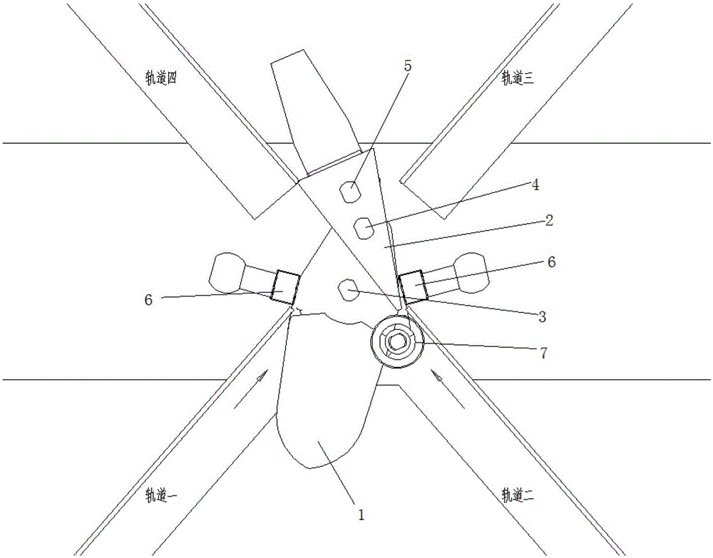
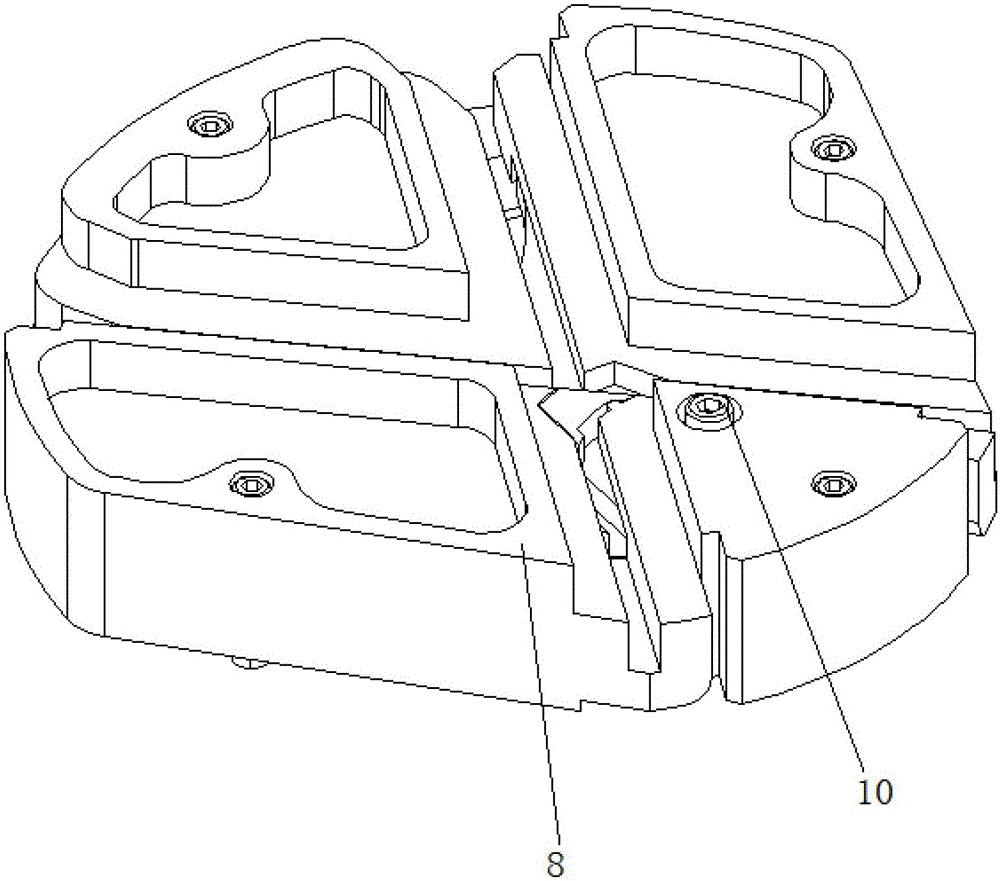
[0032] Such as Figure 3-6 As shown, the central automatic switch reversing device in the slider type sorter of the present invention consists of three main parts in total, including: a fixed plate 8, a guide reversing plate 9 and a rotating shaft 10, wherein there are four on the fixed plate Tracks are track 1, track 2, track 3, and track 4. Track 1 and track 3 are on the same straight line, track 2 and track 4 are on the same straight line, and the straight lines where track 1 and track 3 are located are the same as track 2 and track 3. The four lines intersect. The guide reversing plate 9 is located in the fan-shaped groove below the fixed plate 8, and is hinged with the fixed plate 8 through the rotating shaft 10. There are two tracks on the guide reversing plate 9, namely, the left track and the right track. 9 rotates around the rotating shaft 10, so that the correspond...


PUM


Abstract

The invention relates to an automatic centrally-mounted road junction reversing device in a sliding block sorter, belonging to the technical field of logistics conveying and sorting. The automatic centrally-mounted road junction reversing device is characterized by comprising a fixed plate and a guiding reversing plate, wherein the fixed plate is provided with four tracks; a first walking trolley moves from a track I to a track III along a straight line a; a second walking trolley moves from a track II to a track IV along a straight line b; the guiding reversing plate is of a triangle structure, a joint of two symmetrical sides is hinged with the fixed plate through a rotating shaft; the center of the rotating shaft is equidistant to the two straight lines, and the side just opposite to the rotating shaft is of an inward bending curve shape; the guiding reversing plate is provided with a left guide rail and a right guide rail; the second walking trolley drives the guiding reversing plate to rotate anticlockwise, till the right guide rail and the straight line b are collinear, the track II and the track IV are connected; and the first walking trolley drives the guiding reversing plate to rotate clockwise, till the left guide rail and the straight line a are collinear, the track I and the track III are connected.

Description

technical field [0001] The invention relates to a logistics conveying and sorting machine, in particular to a mid-mounted automatic switch reversing device in a slider type sorting machine, which belongs to the technical field of logistics conveying and sorting. Background technique [0002] In the prior art, using the rollers to walk in the fixed track or guide rail can make the objects or workpieces connected by the rollers move according to the preset path. This technology is widely used in transportation and conveying technology, but when the two tracks are in the same plane When crossing occurs, it is necessary to set an automatic reversing mechanism at the crossing part, corresponding to a designated track at a designated time, so that the designated track constitutes a complete passage, most of the passage conversion members or similar devices in the prior art need The conversion is achieved by means of external force. The components that need to use external force to...

Claims


Application Information

Patent Timeline
Patent Type & Authority Patents(China)
IPC IPC(8): B65G47/22B65G47/52
Inventor 韩先成白振成王德健
Owner SHANGHAI DAMON LOGISTICS TECH
Why Eureka
Try Eureka