Transport device comprising a transverse lifting unit with transport rollers

A technology of conveying device and conveying roller, which is applied in the directions of packaging, conveyor, conveyer objects, etc., can solve the problem of high cost, and achieve the effect of economical cost and simplified installation.

Inactive Publication Date: 2013-03-06
ROBERT BOSCH GMBH
View PDF6 Cites 17 Cited by
  • Summary
  • Abstract
  • Description
  • Claims
  • Application Information

AI Technical Summary

Problems solved by technology

The disadvantage of these constructions is that the construct

Method used


Image

  • Transport device comprising a transverse lifting unit with transport rollers
  • Transport device comprising a transverse lifting unit with transport rollers
  • Transport device comprising a transverse lifting unit with transport rollers

Examples


Example Embodiment

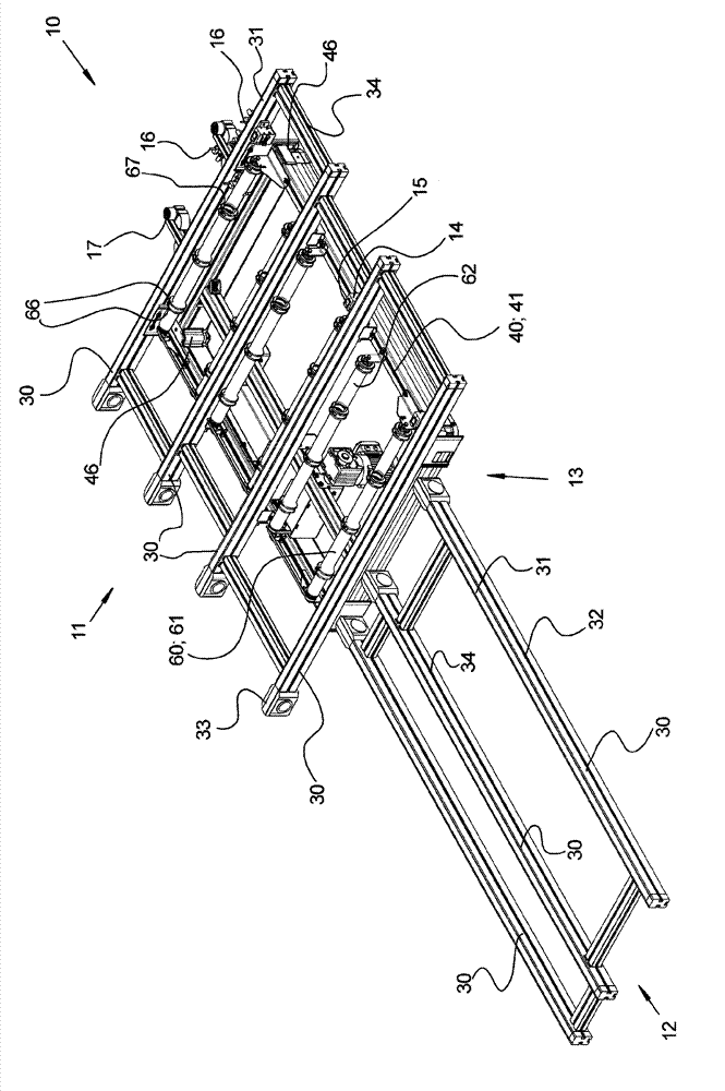
[0022] figure 1 A perspective view of the conveying device 10 according to the invention is shown. The conveying device 10 includes a first conveying section 11 and a second conveying section 12, and the second conveying section diverges perpendicularly from the first conveying section 11. The first conveying section 11 includes four parallel conveying belts 31, and the second conveying section 12 includes three parallel conveying belts 31. The conveyor belts 31 are respectively constructed in the form of conveyor modules 30 according to DE 20 2008 011 613 U1. All the contents of DE 20 2008 011 613 U1 are involved and become the contents of this application.

[0023] All conveying modules 30 are constructed essentially the same, wherein the conveying modules 30 of the first and second conveying sections 11; 12 differ only in their length. Each conveying module 30 includes a supporting profile 32, which is made of aluminum by extrusion. The continuous conveyor belt 31 is guided...


PUM


Abstract

The device (10) has two conveying paths (11, 12) comprising respective conveyor belts (31) that define a conveying plane. A transfer device (40) is arranged in an intersection area between the paths, and comprises a lifting frame (41) moved perpendicular to the plane. The frame extends over entire breadth of the conveying paths, and a conveying unit is arranged on the frame such that goods are rerouted from one of the paths to another path. The belts cross the frame without interrupting the former path. The conveying unit has conveying rollers (60) that are arranged parallel to the belts.

Description

technical field [0001] The invention relates to a delivery device according to the preamble of claim 1 . Background technique [0002] From the catalog “TS 2pv” (version 2.0; phase 04 / 2011; order number: 3 842 540 431 ) of Bosch Rexroth AG, a conveyor device is known for producing solar modules using the thin-film method (Dünnschichtverfahren). The task of such conveying devices is primarily to transport large-area glass panes within production plants for solar modules. The conveyor device comprises a plurality of conveyor belts, the construction of which is the subject of DE 20 2008 011 613 U1. Due to their large width, the glass panes are usually carried by three or more parallel, continuously running conveyor belts, each conveyor belt itself being only for example 40 mm wide. The lift-transverse unit (Hub-Quereinheit) LTS / NT is described on pages 3-5 of the catalog. It connects a first conveyor section with a second conveyor section which diverges perpendicularly from ...

Claims


Application Information

Patent Timeline
IPC IPC(8): B65G47/54B65G49/06
CPCB65G2201/022B65G2207/14B65G47/53
Inventor V.波尔策M.维利P.路德维希H-P.布陶
Owner ROBERT BOSCH GMBH
Why Eureka
Try Eureka