

Automatic can taking device
An automatic, top-down technology, applied in household refrigeration devices, coolers, lighting and heating equipment, etc., can solve the problems of inconvenient access, high investment cost of facilities, disgust of operators, etc., to achieve economical cost, simple structure
- Summary
- Abstract
- Description
- Claims
- Application Information
AI Technical Summary
Problems solved by technology
Method used
Image

Examples
Embodiment Construction
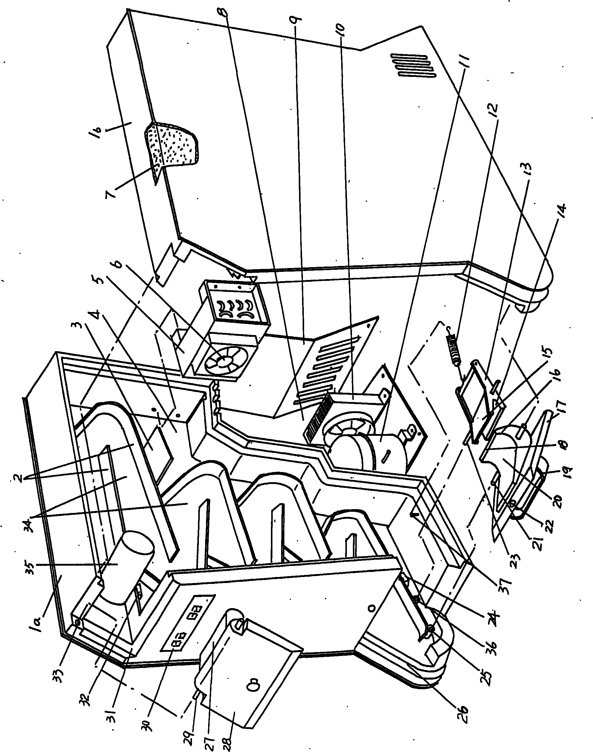
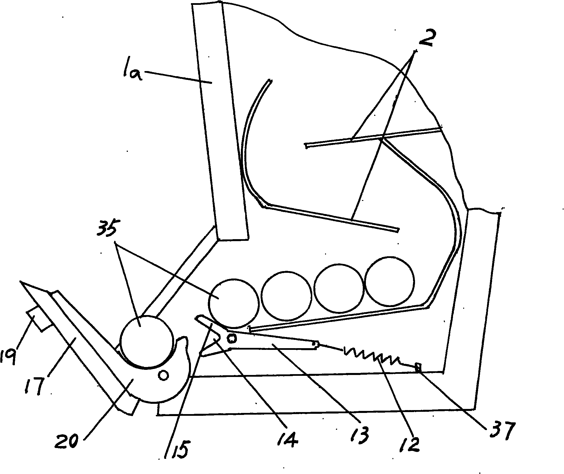
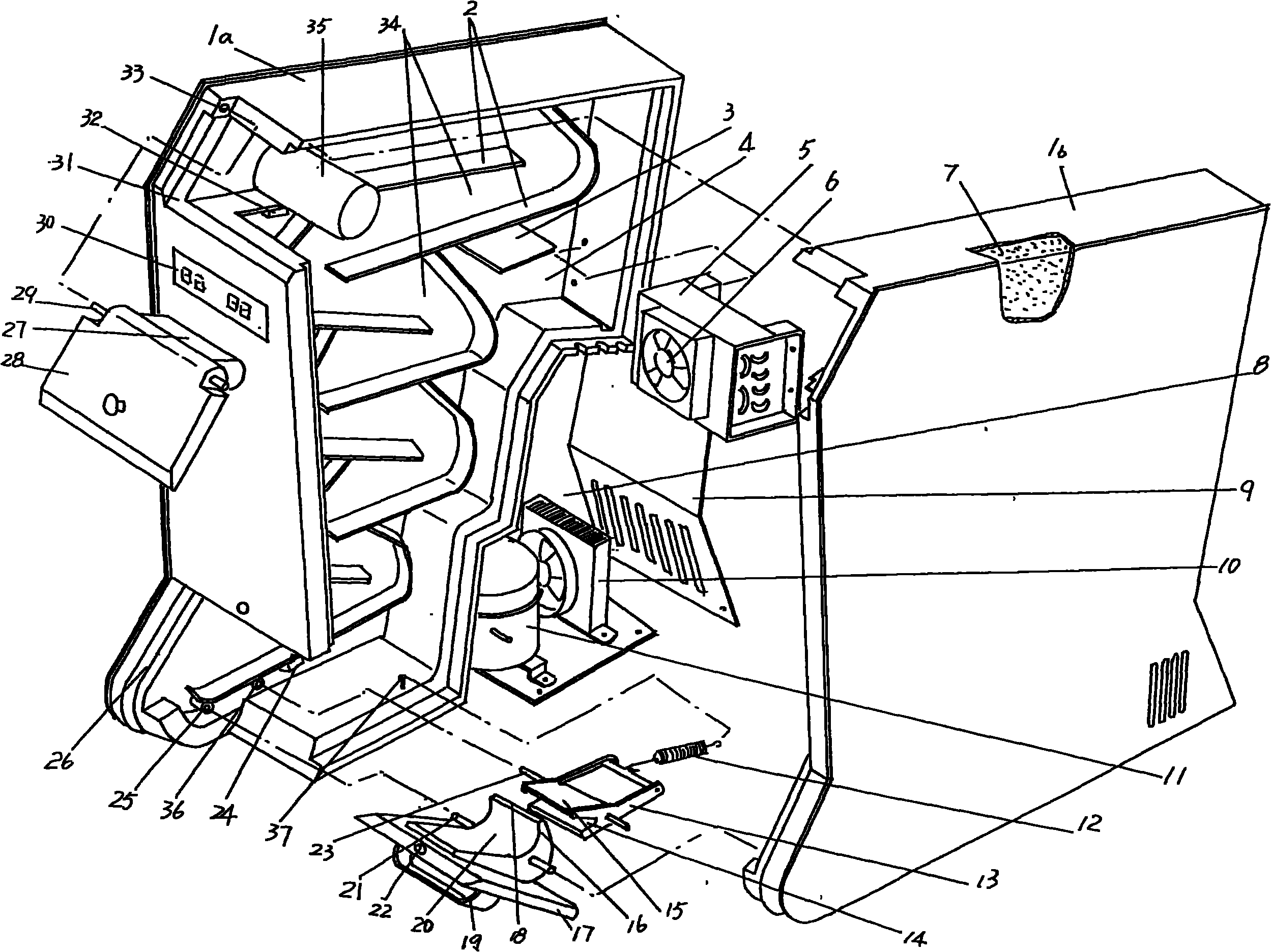
[0018] refer to figure 1 , a pair of left and right box bodies 1a, 1b each have 1 / 2 of the cavity, after they are merged face to face to form a complete whole box body, then the respective 1 / 2 cavity constitutes a The overall cavity 34 gradually narrows from top to bottom. A group of raceways 2 gradually become shorter from top to bottom. The raceway 2 fixed on the inner wall of the left box body 1a is clearly shown in the figure, and the raceway 2 on the inner wall of the right box body 1b is not given but It is perfectly possible to know that both are the same. Moreover, the raceway 2 shown in the figure uses a flat metal or non-metal material, but it can also use a cylindrical metal or non-metal material, no matter what kind of material is used for the raceway 2, as long as it can meet the support The required strength of the pop can 35 is sufficient. In order to facilitate people's understanding, the applicant has also provided a pop can 35 at the starting point of the ...
PUM
 Abstract
Description
Claims
Application Information