

Gene chip detection method on basis of micro and nano magnetic heads
The technology of a gene chip and a detection method is applied in the field of gene chip detection, and achieves the effects of broad application prospects, low preparation cost and economical cost.
- Summary
- Abstract
- Description
- Claims
- Application Information
AI Technical Summary
Problems solved by technology
Method used
Image

Examples
Embodiment 1
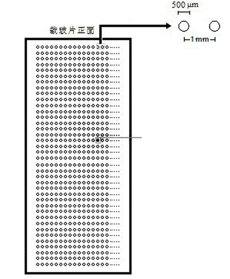
[0026] Example 1: Preparation of rectangular chips
[0027] Such as figure 1 The rectangular chip shown can be commercialized and obtained by in-situ synthesis, such as Affymetrix, or it can be obtained by the laboratory itself using a spotting instrument. Among them, the spot size is 500μm, and the distance between spots is 1mm. The size of the spots and the distance between them determine the basic unit in the scanning process of the subsequent scanner. The laboratory preparation process is as follows:
[0028] The surface treatment of the chip carrier: use the glass slide commonly used in the laboratory, put it in a 1:1 mixed solution of methanol and hydrochloric acid, and soak for 30 minutes before use. After washing with double distilled water, soak the slides in concentrated sulfuric acid for 30 minutes. First use double distilled water and then 95% ethanol to fully rinse the slides to clean the remaining acid on the surface, and then blow dry the liquid. The 95% ethanol...
Embodiment 2
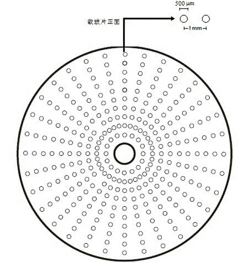
[0036] Example 2: Preparation of round glass slide chip
[0037] Such as figure 2 As shown, from the appearance of the core chip, it is a bit similar to the usual record, that is, it is a circular carrier with a hollow center. From the perspective of the preparation method, the same can refer to the traditional rectangular chip preparation process, using a spotter to spot or in-situ synthesis. The difference is that the sample spots will be arranged along the circumference of concentric circles in a certain size and interval.
[0038] The round glass slide is exactly the same in material as the commonly used glass slide, the difference is its appearance. When spotting, you can use a special spotting instrument to take the center of the circle as the center and perform high-density spotting along the circumference of the disc with different radii. To simplify the process in this embodiment, manual spotting is used directly. The pre-treatment of the glass slide is the same as in...
Embodiment 3
[0040] Example 3: Sample preparation
[0041] Mix 2ml of the pre-prepared Pd colloid solution (average particle size of 10nm) with 1OD sulfhydryl probe P1 (Pd-5'-HS-AGC TCT CAAACT TTT-3', the final concentration of which is about 3.51μM), Incubate for 16h at room temperature. Add 3ml of phosphate buffer (10mM PB, 0.1M NaCl, pH 7), and continue to incubate for 48h. Then centrifuge at 14000 rpm for 25 min to separate unlabeled DNA. After centrifugation, the supernatant was removed. The black precipitate in the bottom layer was diluted with 5ml phosphate buffer (10mM PB, 0.1M NaCl, pH7) again, centrifuged again at 14000rpm for 25min, and the supernatant was removed. The lower black precipitate was added with 1ml of 2×PBS ( 10mM PB, 0.3M NaCl, pH 7), the mother liquor is stored at 4°C for later use.
[0042] The above process of labeling the sample with nano-Pd can also be obtained through the following scheme: First, the obtained Pd-S-(CH 2 ) 5 -COOH solution, dispersed in 1ml MES ...
PUM
 Abstract
Description
Claims
Application Information