
Tension adjusting mechanism of loom

A tension adjustment mechanism and loom technology, which are applied in the directions of winding strips, thin material processing, transportation and packaging, etc., can solve the problems of poor weaving effect, no tension adjustment structure, etc., and achieve good effects.

Inactive Publication Date: 2013-03-06
WUJIAN RUNFENG SILK FINISHING CO LTD
View PDF7 Cites 0 Cited by
  • Summary
  • Abstract
  • Description
  • Claims
  • Application Information

AI Technical Summary

Problems solved by technology

[0002] In the prior art, the cloth winding machine is usually not equipped with a tension adjustment structure, and the weaving effect is poor

Method used


Image

  • Tension adjusting mechanism of loom

Examples


Embodiment Construction

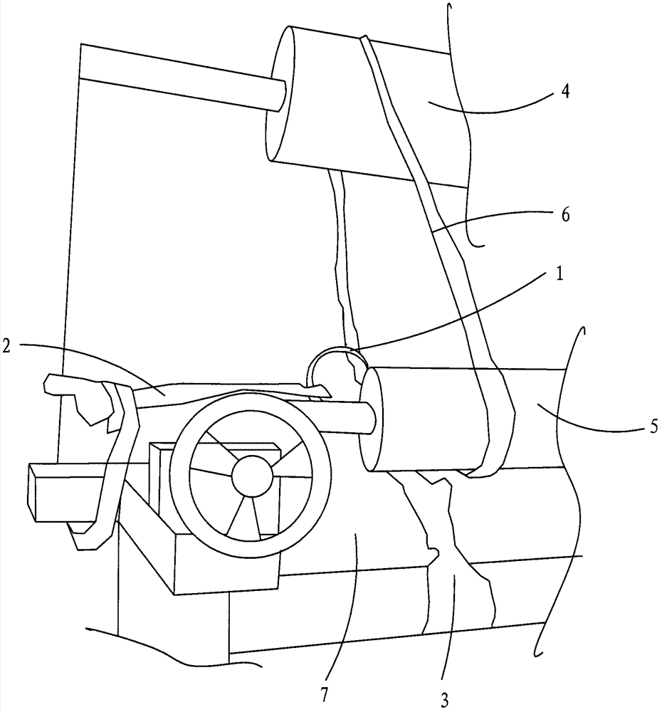
[0010] as attached figure 1 As shown, a tension adjustment mechanism of a loom includes an iron ring 1, a first traction rope 2 connected to the iron ring 1 at one end, and a second traction rope 2 connected at one end to the iron ring 1. The traction rope 3, the third traction rope 6 that passes through the iron ring 1 and is wound on the upper roll 4 and the lower roll 5, the other end of the first traction rope 2 part is fixedly connected with the frame 7, and the other end of the second traction rope 3 is fixedly connected with the frame 7.

[0011] The iron ring 1 is a closed iron ring 1 .

[0012] As mentioned above, we have fully described according to the purpose of the present invention, but the present invention is not limited to the above-mentioned embodiments and implementation methods. Practitioners in the relevant technical fields may make various changes and implementations within the scope permitted by the technical ideas of the present invention.


PUM


Abstract

The invention discloses a tension adjusting mechanism of a loom. The tension adjusting mechanism comprises an iron ring, a first pulling rope, a second pulling rope and a third pulling rope, wherein one end of the first pulling rope is connected with the iron ring; one end of the second pulling rope is connected with the iron ring; the third pulling rope is threaded through the iron ring and wound on an upper winding roller and a lower winding roller; the other end of the first pulling rope is fixedly connected with a rack; and the other end of the second pulling rope is fixedly connected with the rack. Through the tension adjusting mechanism, the weaving effect is better.

Description

technical field [0001] The invention relates to a tension regulating mechanism of a loom. Background technique [0002] The cloth rolling machine in the prior art is usually not provided with a tension adjustment structure, and the weaving effect is relatively poor. Contents of the invention [0003] The technical problem to be solved by the present invention is to provide a tension regulating mechanism of a loom. [0004] In order to solve the above-mentioned technical problems, a technical solution adopted by the present invention is: a tension adjustment mechanism of a loom, comprising an iron ring, a first traction rope with one end connected to the iron ring, one end connected to the The second traction rope connected with the iron hoop, the third traction rope that passes through the iron hoop and is wound on the upper winding roller and the lower winding roller, and the first traction rope The other end of the second traction rope is fixedly connected to the frame...

Claims


Application Information

Patent Timeline
Patent Type & Authority Applications(China)
IPC IPC(8): B65H23/00
Inventor 郭良
Owner WUJIAN RUNFENG SILK FINISHING CO LTD
Learn More