Buckled rapid joint

A crimping and fast technology, applied in the direction of pipes/pipe joints/fittings, hose connection devices, mechanical equipment, etc., can solve the problems of narrowing the scope of application, more sealing, and lower overall efficiency, and achieve a simple and compact structure. , good sealing, easy to loosen

Inactive Publication Date: 2013-03-06
ZHEJIANG BOSHITE MECHANICAL CO LTD
View PDF8 Cites 2 Cited by
  • Summary
  • Abstract
  • Description
  • Claims
  • Application Information

AI Technical Summary

Problems solved by technology

The structural disadvantage of these joints is that it is impossible to realize the one-time connection between the pipe body and the joint, but the structure must be installed twice to realize the connection, which adds a hidden danger to the sealing of the connection.
[0004] For this reason, there are deficiencies in the quick connectors currently used in automobile braking systems. On the one hand, after the pipe fittings are connected during use, the buckle is not firm, and the rear end is left in the quick connector after being pulled off, which affects later use; , which is the most serious problem, is air leakage. Once there is air leakage due to poor sealing, this will affect the use of the car braking system. There are potential safety hazards, which cannot be underestimated and need to be improved.
[0005] In addition, due to the different angles during the installation process, and the existing structure cannot be rotated to meet different angle requirements, the scope of application is narrowed and the overall efficiency is reduced

Method used


Image

  • Buckled rapid joint
  • Buckled rapid joint
  • Buckled rapid joint

Examples


Embodiment Construction

[0040]

[0041] The present invention will be further described below in conjunction with the accompanying drawings and embodiments.

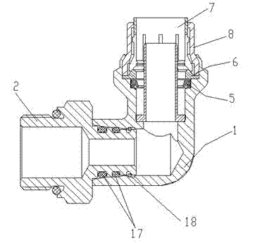
[0042] Reference attached figure 1 To attach Figure 7 As shown, this embodiment discloses a buckle-type quick connector, including a connector 1, characterized in that: a stopper structure is formed at one end of the connector 1, a buckle structure is provided on the stopper structure, and a buckle structure is formed on the inner wall of the other end. A clamping groove structure, the clamping groove structure is provided with a matching quick-connect nut structure.

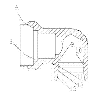
[0043] It is further provided that the stopper structure includes a first stopper 3 formed on the inner wall of the joint, and a second stopper 4 formed above the first stopper 3 .

[0044] It is further provided that the buckle structure includes a lip seal 5 arranged on the first block 3, a pressure ring 6 is provided on the lip seal 5, and a ferrule 7 is provided ou...


PUM


Abstract

The invention discloses a buckled rapid joint, which comprises a joint, wherein a blocking table structure is formed at one end of the joint, and is provided with a buckling structure; a clamping groove structure is formed on the inner wall of the other end of the joint; and the clamping groove structure is provided with rapid-joint nut structures which are arranged in a matching way. The buckled rapid joint has the advantages of simple and delicate structure, good airtightness, firm clamping, easiness in loosening and capability of realizing repeated loosening and clamping; and meanwhile, multi-angle rotation can be realized, and the installation azimuth angle of the joint can be changed optionally by 360 degrees to adapt to different installation requirements.

Description

Technical field [0001] The invention involves a type of fast -moving fast connector. Background technique [0002] The hose connector is the main component component in various pipeline connections. It is mainly used to connect the pipeline connection of the device pipe interface and the hose, but the existing device pipeline connector imports generally use card sleeve threads and expansion type type expansion type types.The thread, welded threads are connected. It is easy to cause tube to twist during installation. Therefore, the rear corner needs to be adjusted. After the installation, the tube can always be changed to the natural extension of the tube.Or the 45 -degree angle standard pipe cannot be used.Due to high manufacturing and assembly costs, it is difficult to adapt to the current assembly line operation due to high manufacturing and assembly process. [0003] The development of foreign automotive fluid system pipeline connections As early as the early 1980s, a fast -lo...

Claims


Application Information

Patent Timeline
Patent Type & Authority Applications(China)
IPC IPC(8): F16L33/24F16L33/18
Inventor 冯波周志翔
Owner ZHEJIANG BOSHITE MECHANICAL CO LTD
Why Eureka
Try Eureka