Optical fiber wiring box and cabinet

A technology of wiring box and fiber cloth, applied in the direction of fiber mechanical structure, etc., can solve the problems of affecting the appearance, damaged fiber, messy fiber wiring, etc.

Inactive Publication Date: 2013-03-06
HUAWEI TECH CO LTD
View PDF6 Cites 2 Cited by
  • Summary
  • Abstract
  • Description
  • Claims
  • Application Information

AI Technical Summary

Problems solved by technology

[0002] In many computer rooms, the wiring of optical fibers is messy, which not only affects the appearance, but also easily damages the optical fibers. To solve this problem, an optical fiber wiring box can be used to place the optical fibers. In the prior art, there is an optical fiber wiring box. There is an optical fiber inlet on the bottom of the box, and an optical fiber outlet on the side plate. A set of winding posts are installed on the inner wall of the box body, and multiple optical fibers can be wound. However, the fiber optic wiring box is large in size, and the installation and replacement process of optical fibers is more complicated.

Method used


Image

  • Optical fiber wiring box and cabinet
  • Optical fiber wiring box and cabinet
  • Optical fiber wiring box and cabinet

Examples


Embodiment Construction

[0031] The technical solutions in the embodiments of the present invention will be clearly and completely described below in conjunction with the accompanying drawings in the embodiments of the present invention. Obviously, the described embodiments are only a part of the embodiments of the present invention, rather than all the embodiments. Based on the embodiments of the present invention, all other embodiments obtained by those of ordinary skill in the art without creative work shall fall within the protection scope of the present invention.

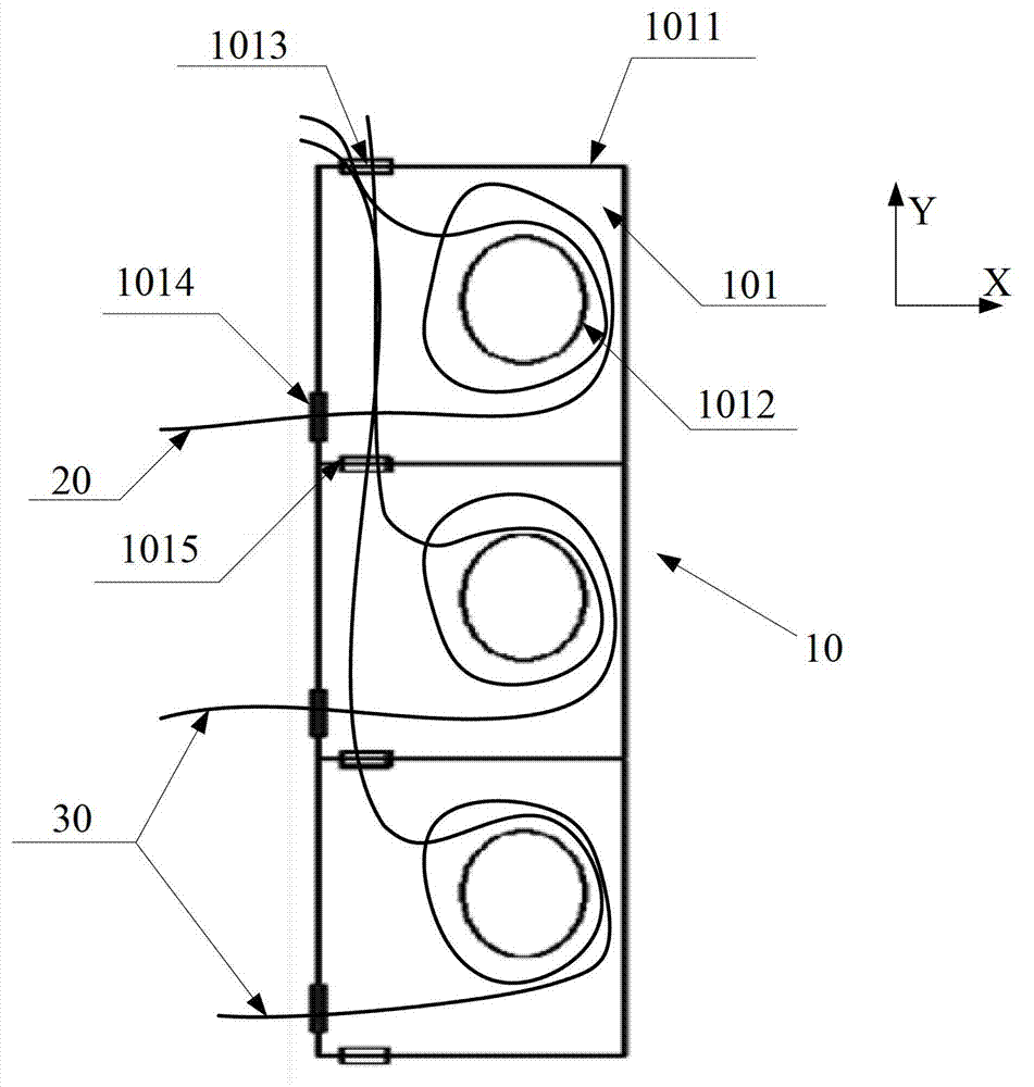
[0032] The embodiment of the present invention provides an optical fiber wiring box 10, such as figure 1 Shown, including:

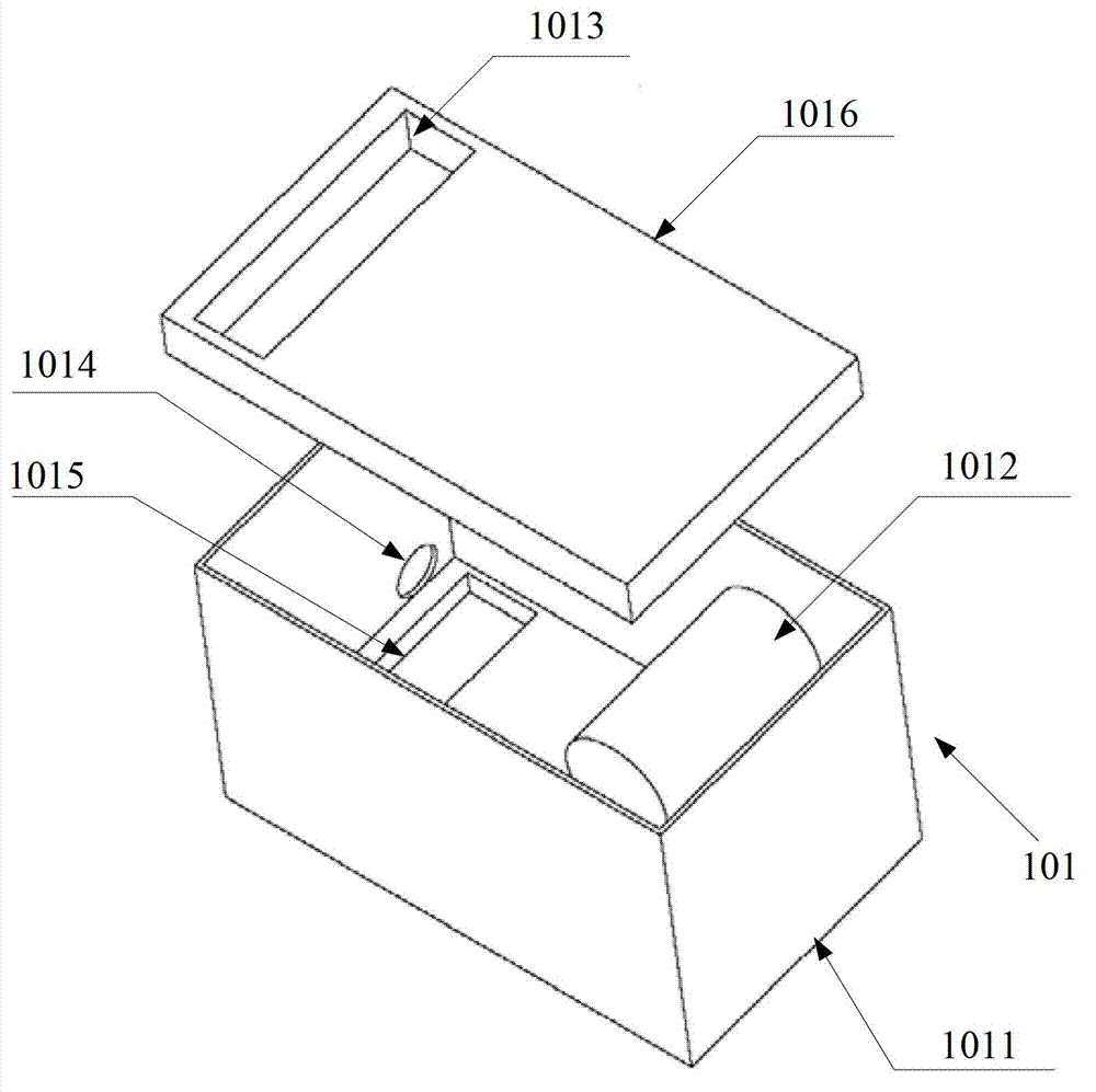
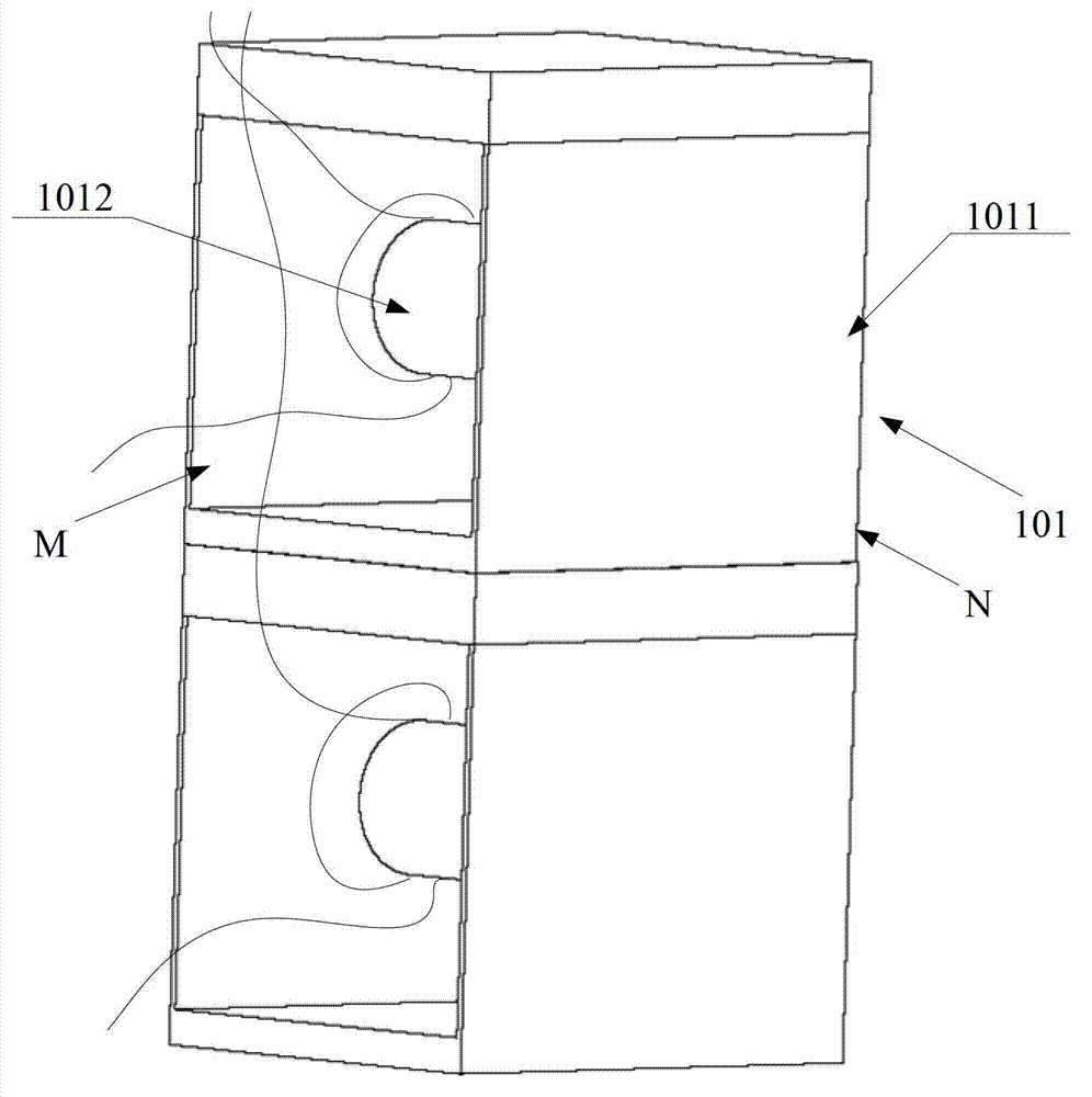
[0033] At least one optical fiber wiring sub-box 101, the optical fiber wiring sub-box 101 includes:

[0034] Box body 1011.

[0035] The winding post 1012 located inside the box body 1011 is used to wind the optical fiber 20 in the box body 1011. The radius of the bobbin 1012 is set with reference to the curvature in ...


PUM


Abstract

The embodiment of the invention provides an optical fiber wiring box and a cabinet, relating to the field of machine design, wherein the volume of the optical fiber wiring box can be flexibly adjusted and the mounting and replacement processes of optical fibers are simplified. The optical fiber wiring box comprises at least one optical fiber wiring sub-box; and each optical fiber wiring sub-box comprises a box body, a wrapping post, an optical fiber inlet, an optical fiber outlet and an auxiliary optical fiber outlet, wherein the wrapping post is positioned on the inner side of the box body and used for winding of an optical fiber in the box body; the optical fiber inlet is formed in the top part of the box body and used for the extending of one end of the optical fiber in the box body; the optical fiber outlet is formed in a side plate of the box body and used for the extending of the other end of the optical fiber in the box body, and the auxiliary optical fiber outlet is formed in the bottom part of the box body; and the optical fiber inlet and the auxiliary optical fiber outlet are used for the running through of one end of each of optical fibers in other optical fiber wiring sub-boxes from the box body. The optical fiber wiring box and the cabinet provided by the invention are used for the wiring of optical fibers.

Description

Technical field [0001] The invention relates to the field of mechanical design, in particular to an optical fiber wiring box and a cabinet. Background technique [0002] In many computer rooms, the optical fiber wiring is messy, which not only affects the appearance, but also easily damages the optical fiber. To solve this problem, an optical fiber wiring box can be used to place the optical fiber. In the prior art, an optical fiber wiring box is used. There is an optical fiber inlet at the bottom of the box and an optical fiber outlet on the side panel. A set of winding posts are installed on the side wall of the box body to wind multiple optical fibers. However, the optical fiber wiring box has a large volume and the installation and replacement process of optical fibers is more complicated. . Summary of the invention [0003] The embodiments of the present invention provide an optical fiber wiring box and a cabinet, which can flexibly adjust the volume of the optical fiber wir...

Claims


Application Information

Patent Timeline
IPC IPC(8): G02B6/44
Inventor 王晓洲
Owner HUAWEI TECH CO LTD
Why Eureka
Try Eureka