

Touch sensor, manufacturing method thereof and display device
A touch sensor and metal layer technology, applied in the direction of instruments, electrical digital data processing, data processing input/output process, etc., can solve the problems of high cost and low production capacity, and achieve the effect of improving production capacity and solving low production capacity
Active Publication Date: 2013-03-06
BEIJING BOE OPTOELECTRONCIS TECH CO LTD
View PDF4 Cites 20 Cited by
- Summary
- Abstract
- Description
- Claims
- Application Information
AI Technical Summary
Problems solved by technology
[0004] Embodiments of the present invention provide a touch sensor, its preparation method, and a display device, which are used to solve the problem of low production capacity caused by six photolithography processes in the existing touch sensor production process, and the need to use six masks to make the cost high The problem
Method used
View moreImage
Smart ImageViewing Examples

Examples
preparation example Construction
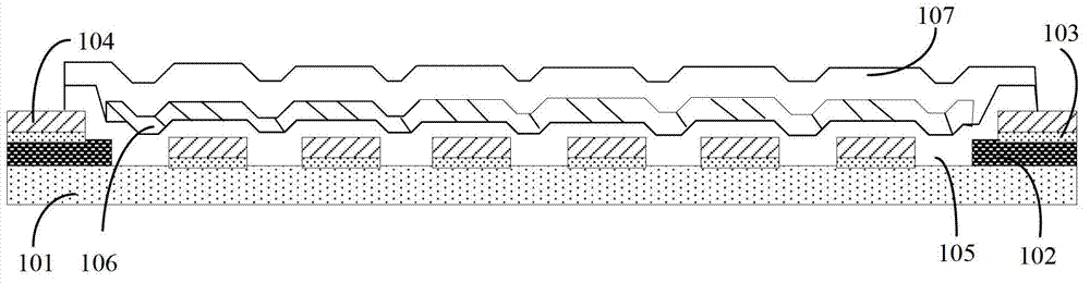
[0043] Based on the same inventive concept, an embodiment of the present invention also provides a method for manufacturing a touch sensor, the method includes the following steps: sequentially preparing a BM layer, a BM protective layer and a metal layer on a transparent substrate, wherein the BM protective layer and the metal layer steps such as Figure 4 As shown, it can be achieved through the following process:
[0044] S401, sequentially depositing a BM protection layer and a metal layer on the BM layer;
[0045] S402, using a mask to form the same pattern on the BM protection layer and the metal layer through a patterning process.
Login to View More PUM
 Abstract
The invention provides a touch sensor, a manufacturing method thereof and a display device. A BM protection layer and a metal layer are provided with same patterns, so that five mask plates are needed in the technical process for producing the touch sensor, and the photoetching operation is implemented for five times, therefore the problem of low productivity caused by using the photoetching technique 6 times and the problem of high cost caused by using 6 mask plates in the production process of the touch sensor in the prior art are solved. The invention relates to the field of design and manufacturing of touch sensors.
Description
technical field [0001] The present invention relates to the field of design and manufacture of touch sensors, in particular to a touch sensor, its preparation method and a display device. Background technique [0002] Currently, touch sensor (Touch sensor) technology can be divided into two glass (G-G, Glass-Glass) touch technology type and single glass touch technology (OGS, One Glass Solution) type. The G-G type is to make the touch sensor on the ordinary glass, and then laminate it with the protective glass. Its advantages are simple manufacturing process and good compatibility with the array (array) production line. However, due to the lamination of double-layer glass, it has the disadvantages of relatively thick thickness and low transmittance. OGS is to make the touch sensor directly on the strengthened glass, which is composed of black matrix (BM, Black Matrix) material that blocks light, protective film (OC, Over Coat) material that plays a protective role, and meta...
Claims
Login to View More Application Information
Patent Timeline
 IPC IPC(8): G06F3/041
Inventor曲连杰郭建
OwnerBEIJING BOE OPTOELECTRONCIS TECH CO LTD