Connector

A technology of connectors and connecting parts, which is applied in the direction of connection, parts of connecting devices, contact parts, etc., can solve the problems of high cost and unfavorable increase of substrate area, and achieve space saving and fewer parts. Effect

Inactive Publication Date: 2013-03-06
YOKOWO CO LTD
View PDF1 Cites 18 Cited by
  • Summary
  • Abstract
  • Description
  • Claims
  • Application Information

AI Technical Summary

Problems solved by technology

[0007] Figure 32 The leaf spring type connector is advantageous in that it can be composed of a minimum of one part, but it is disadvantageous in that it occupies an increased board area when the position of the contact point is increased.
Figure 33 The pin connector with the Figure 32 Compared with the leaf spring type connector, it is advantageous in that it does not occupy the board area even if the contact point position is high. On the other hand, in addition to the coil spring and the pin as the contact point, they need to be held and used for Since the tube mounted on the circuit board is composed of at least three parts, it is disadvantageous in that the cost increases

Method used


Image

  • Connector
  • Connector
  • Connector

Examples


Embodiment Construction

[0070] Hereinafter, preferred embodiments of the present invention will be described in detail with reference to the drawings. It should be noted that the same or equivalent structural elements, members, and the like shown in the drawings are given the same reference numerals, and overlapping descriptions are appropriately omitted. In addition, the embodiment does not limit the invention but is an example, and all the features and combinations thereof described in the embodiment are not necessarily essential features of the invention.

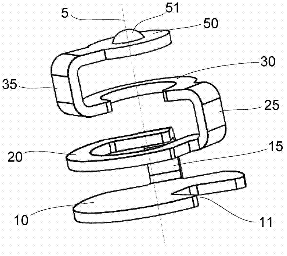
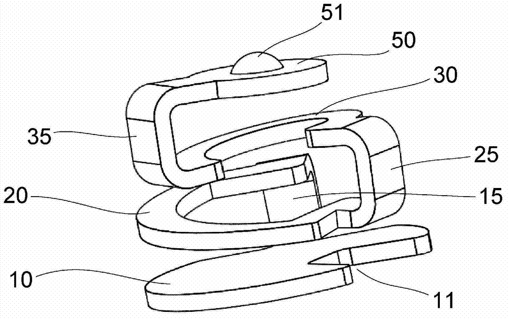
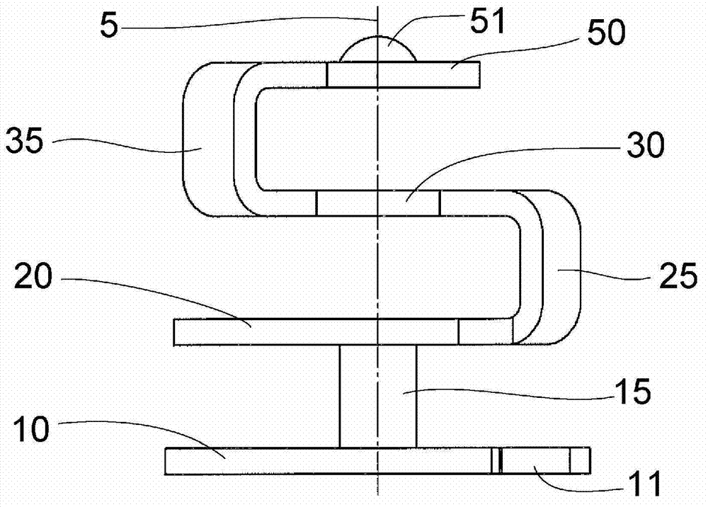
[0071] figure 1 It is a perspective view of the extended state of the connector according to Embodiment 1 of the present invention. figure 2 is a perspective view of the connector in a compressed state. image 3 is a front view of the connector in its extended state. Figure 4 is a top view of the connector in its extended state, Figure 5 is the bottom view of the connector in its extended state, Image 6 is the left side view of the co...


PUM


Abstract

The invention provides a connector which can meanwhile reduce member quantity and save space. The connector is installed in a circuit substrate by using a bottom surface of a base position (10) as a contact surface. A phantom line (5) interconnecting centers of the base position (10) and a front end protrusion part (51) is defined. A first rotary part (20) rotates in an arc shape around the phantom line (5) by using the phantom line (5) as an axis. A second rotary part (30) rotates in an arc shape around the phantom line (5) by using the phantom line (5) as an axis. A rotation angle of the first rotary part (20) and the second rotary part (30) is about 240 DEG.

Description

technical field [0001] The present invention relates to a connector provided on, for example, a printed board and used to electrically connect conductive patterns such as a basic pattern and a wiring pattern of the printed board to conductive patterns and shielding cases of another printed board. Background technique [0002] Figure 32 It is an external view of a conventional leaf spring type connector obtained by bending a metal plate when it is attached to a board (see also Patent Document 1 below). This connector is mounted on the circuit board 2 by soldering or the like with the mounting surface 813 as the contact surface, and the contact point portion 814 is in contact with the shield case or the like. The elastic force of the elastic deformation portion 815 becomes the contact force. [0003] Figure 33 It is an external view of a conventional pin connector that obtains elasticity by compression of a coil spring when it is attached to a board. This connector is moun...

Claims


Application Information

Patent Timeline
Patent Type & Authority Applications(China)
IPC IPC(8): H01R13/24
CPCH01R13/2421
Inventor 石塚真一添岛良介
Owner YOKOWO CO LTD
Why Eureka
Try Eureka