Cages for Radial Roller Bearings

A roller bearing and cage technology, which is applied in the field of cages for radial roller bearings, can solve problems such as easy skew and instability, and achieve the effect of inhibiting wear

Active Publication Date: 2016-05-04
NSK LTD
View PDF11 Cites 0 Cited by
  • Summary
  • Abstract
  • Description
  • Claims
  • Application Information

AI Technical Summary

Problems solved by technology

In addition, the rollers held in the pockets 10 in the vicinity of both ends of the retainer 7b with the sandwiching slits 18c and 18d are prone to be skewed.
As a result, there is a possibility that the behavior of the retainer 7b becomes unstable

Method used


Image

  • Cages for Radial Roller Bearings
  • Cages for Radial Roller Bearings
  • Cages for Radial Roller Bearings

Examples


Embodiment Construction

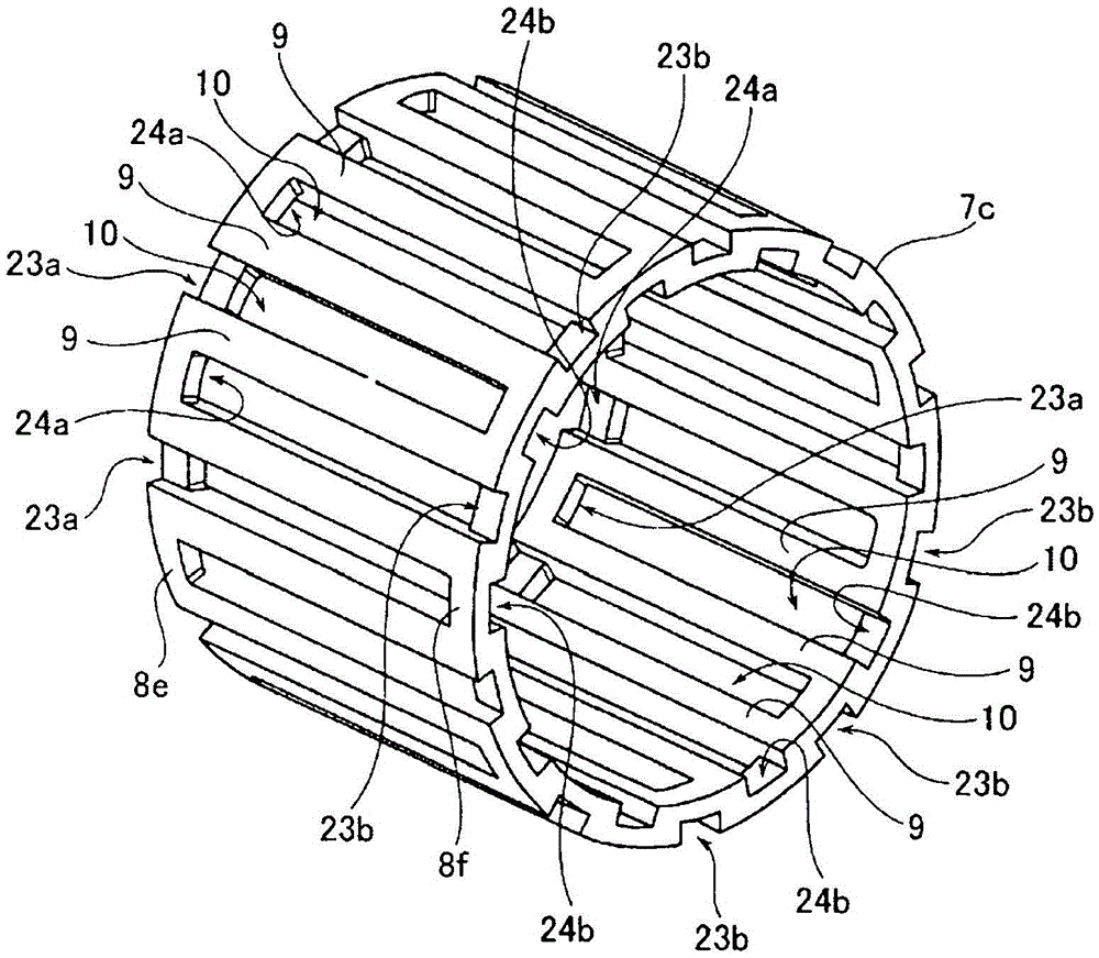
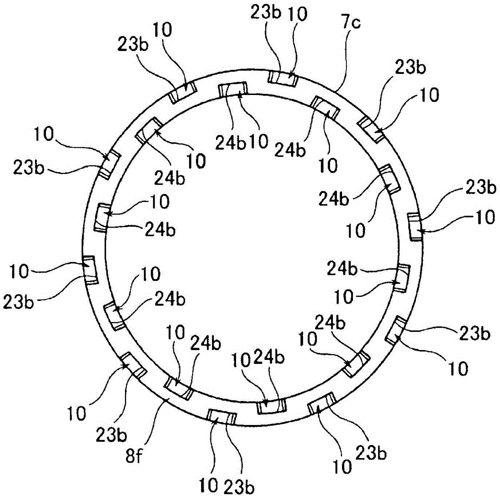
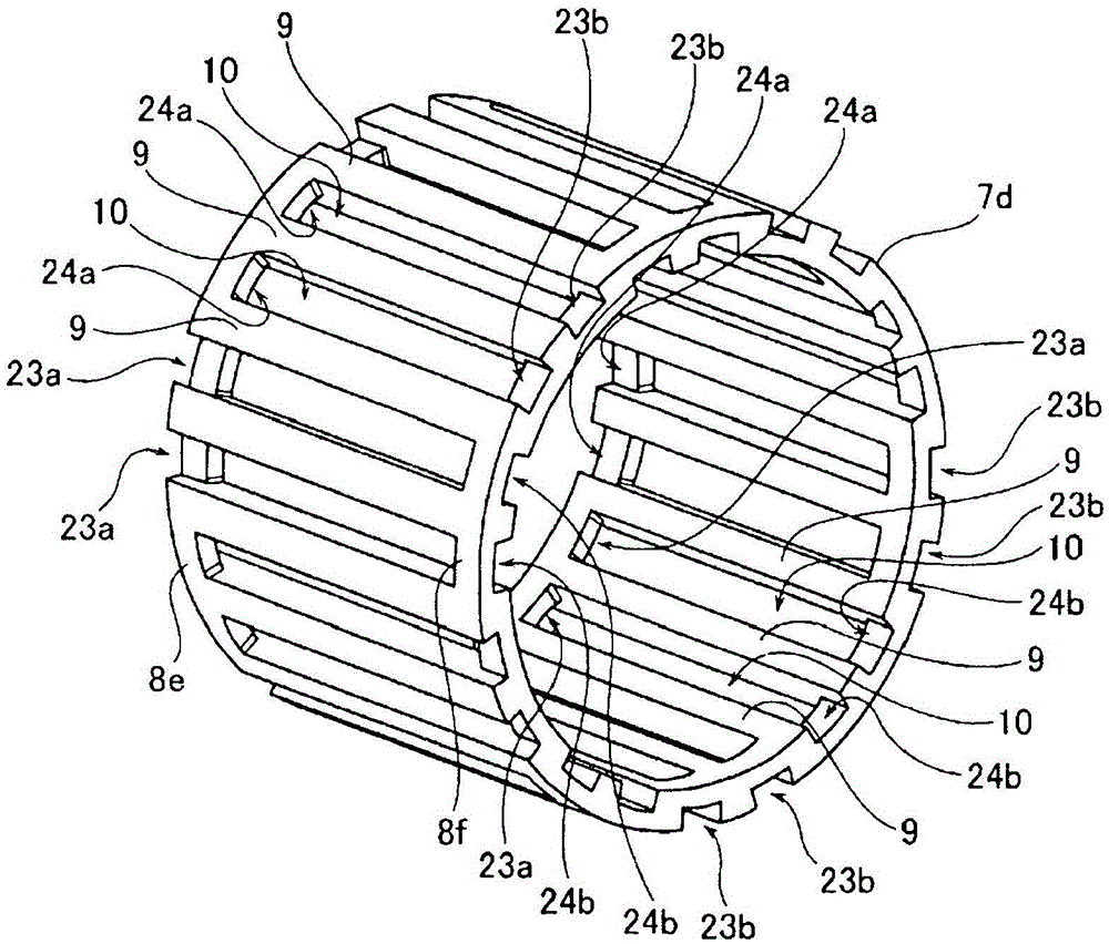
[0090] Next, a cage for a radial roller bearing according to the present invention will be described with reference to the drawings. The radial roller bearing incorporating the cage for radial roller bearing of the present invention is equipped with an outer diameter side member having a cylindrical outer ring track on the inner peripheral surface (an outer member that does not rotate during use). Rings, bearing housings, or gears, rollers, etc. that rotate during use); the inner diameter side member that is arranged on the inner diameter side of the outer diameter side member and has a cylindrical inner ring track on its outer peripheral surface (the inner ring that rotates during use , a rotating shaft or a support shaft that does not rotate during use, etc.), and a plurality of rollers (including needle rollers) that are freely rotatable provided between these outer ring tracks and inner ring tracks. In addition, the size of the radial roller bearing, the presence or absenc...


PUM


Abstract

The present invention is a radial roller bearing cage manufactured by axial core-pulling forming. Even when the guide surface of the counterpart member cannot support the entire area of ​​the axial end surface of the radial roller bearing cage, It is also possible to suppress abrasion of the axial end surface due to friction with the guide surface regardless of the assembly direction. The retainer (7c) is composed of a pair of annular edge portions (8e, 8f) and a plurality of pillars (9), and the adjacent pillars (9) in the circumferential direction are formed into pockets ( 10). On the edge (8e, 8f), the outer diameter side recesses (23a, 23b) are provided at multiple positions of the part of the outer peripheral surface that is aligned with the pocket hole (10) in the axial direction, and the inner peripheral surface and the pocket The hole ( 10 ) is provided with inner diameter side recesses ( 24 a , 24 b ) at a plurality of locations in the axially aligned portion that are out of phase with the outer diameter side recesses ( 23 a , 23 b ) in the circumferential direction. In addition, the phases in the circumferential direction of the outer diameter side recesses (23a, 23b) and the inner diameter side recesses (24a, 24b) are different in the one edge (8e) and the other edge (8f).

Description

technical field [0001] The present invention relates to a radial roller bearing cage manufactured by axial core pulling (Japanese: アキシャルドロー) forming, and the radial roller bearing cage is incorporated into a transmission for a motor vehicle or the like. In radial roller bearings. Background technique [0002] A large load is applied in the radial direction during operation to the rotary support portion of various power mechanisms included in vehicles such as automobiles and railway vehicles. Therefore, as a bearing incorporated in such a rotation support portion, Figure 24 The radial roller bearing 1 excellent in radial load bearing capacity as shown has been widely used in the past. [0003] The radial roller bearing 1 is formed by a cylindrical outer ring raceway 3 provided on the inner peripheral surface of an outer radial side member 2 such as a bearing housing that does not rotate during use, and a shaft 4 provided on a rotating shaft or the like. A plurality of roll...

Claims


Application Information

Patent Timeline
Patent Type & Authority Patents(China)
IPC IPC(8): F16C33/46F16C19/26F16C33/50F16C33/51
CPCF16C19/48F16C33/4635F16C33/4694F16C33/516F16C2240/46F16C2361/61F16C19/26F16C33/46F16C33/50F16C33/51
Inventor 石桥丰
Owner NSK LTD
Why Eureka
Try Eureka