Bottom bent aeration facility

A bottom plate, curved technology, applied in the field of curved aeration facilities under the bottom plate, can solve the problems such as the reduction of the aeration protection length, the influence of the flow pattern of the downstream discharge groove, and the poor flow pattern, so as to improve the downstream flow pattern and improve the water flow. Flow state, avoid the effect of cavity backwater

Active Publication Date: 2016-05-04
POWERCHINA XIBEI ENG
View PDF6 Cites 0 Cited by
  • Summary
  • Abstract
  • Description
  • Claims
  • Application Information

AI Technical Summary

Problems solved by technology

[0004] In addition, for discharge structures such as spillways with large bottom slopes, although water accumulation is not easy to occur in the aerated cavity, the setting of the aerated sill changes the water surface line of the original discharge channel, which will definitely affect the downstream discharge channel. Fluid influence
Therefore, when the water depth in the chute changes greatly, the setting of the aeration sill will face such a problem: that is, if the water depth is large, enough aeration cavities can be formed, and when the water depth is small, the downstream of the aeration sill will often form a larger cavity. Strong water splashing, the flow state is poor; on the contrary, if the water depth is small, the flow state of the chute is good, and when the water depth is large, sufficient aeration cavity cannot be formed, and the aeration protection length is reduced
Therefore, how to set up a reasonable aeration facility so that it can better adapt to changes in the water depth of the chute can not only ensure a good aeration effect, but also make the water flow in the downstream chute as smooth as possible without splashing water. Another difficult problem in the research on the size of gas facilities, and this problem cannot be solved by using conventional aeration sills or even special-shaped aeration sills

Method used


Image

  • Bottom bent aeration facility
  • Bottom bent aeration facility
  • Bottom bent aeration facility

Examples


Embodiment 1

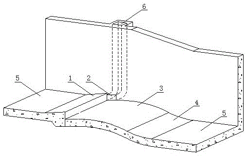
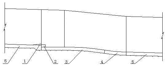
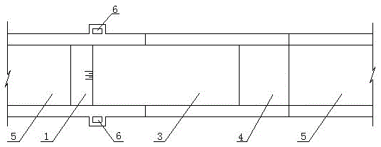
[0019] Such as figure 1 , figure 2 and image 3 As shown, the floor-curved aeration facility is a part of the floor 5 of the flood discharge building, that is, the floor-curved aeration facility is embedded in the floor 5 as a whole.

[0020] The under-bent type aeration facility at least includes an aeration sill 1, a ventilation hole 2, an under-bent section 3 and an anti-arc section 4, and the aeration sill 1, the under-bend section 3 and the anti-arc section 4 are sequentially spliced ​​together, that is The upstream of the aeration ridge 1 is connected to the upper end of the bottom slope 5, and its downstream is connected to the upstream of the bottom bend section 3. The lower end is connected, and the ventilation hole 2 is arranged on both sides of the downstream of the aeration rim 1 .

[0021] Among them, the aerated sill 1 adopts the combination of the sill and the sill, the height of the sill is 0.1m to 0.5m, the sill angle is 5° to 7°, and the height of the sil...

Embodiment 2

[0027] The structure of this embodiment is basically the same as that of Embodiment 1, the difference is that a section of horizontal section is set between the aeration sill 1 and the lower bending section 3 of the bottom plate, its length is 3.5 meters to 10 meters, and its length is proportional to the water flow Fr value. Proportional, that is, the greater the value of the water flow Fr, the greater the length, and the horizontal section makes the aeration ridge 1 pick up the water and fall on the middle and rear part of the lower curved section 3 of the bottom plate.

[0028] The invention is not only suitable for discharge structures with relatively gentle bottom slopes, which can eliminate water accumulation in air-entrained cavities, but also suitable for relatively steep bottom slopes, which can maintain good water flow state at various water depths.


PUM


Abstract

The invention relates to the field of flood discharge buildings and provides an aeration facility with a downward-bent base slab. The aeration facility at least comprises an aerator, vent holes, a base slab downward-bent section and an ogee section and is characterized in that the aerator, the base slab downward-bent section and the ogee section are sequentially arranged to form a whole, and the spliced whole is one part of a base slab; the vent holes are formed on the two downstream sides of the aerator and are communicated with a ventilation shaft and a ventilation corridor or directly communicated with the air; the aerator is combined by a flip bucket and a drop sill; the base slab downward-bent section is one section of arc curve and has a radius of 80-150 meters and a central angle of 6-10 degrees, the upper part of the base slab downward-bent section is connected with the lower part of the aerator, and the lower part of the base slab downward-bent section is connected with the upper part of the ogee section; and the radius value of the ogee section is three-six times of the water depth of the cross section. The aeration facility is not only suitable for spillage buildings with gradual base slopes, but also is suitable for steep base slopes, so that an excellent water flow state can be kept in various depths.

Description

technical field [0001] The invention relates to the field of flood discharge buildings, and is a bottom-bent type aeration facility. Background technique [0002] For flood discharge structures with high water heads, cavitation and cavitation damage are prone to occur on the flowing side wall. Aeration facilities are usually required in the project to promote aeration of the water flow and prevent the occurrence of cavitation damage on the wall surface. [0003] Maintaining a stable air intake cavity is the prerequisite for the aeration facility to perform its normal functions. If the cavity is unstable or the intake channel is blocked by accumulated water, the aeration facility will not be able to aerate and reduce corrosion. On the contrary, it will become a source of cavitation, causing or aggravating the cavitation and cavitation damage of buildings. Therefore, eliminating backwater in the cavity and ensuring smooth ventilation are the keys to the success of the aeratio...

Claims


Application Information

Patent Timeline
Patent Type & Authority Patents(China)
IPC IPC(8): E02B8/06
Inventor 刘少斌卫勇
Owner POWERCHINA XIBEI ENG
Why Eureka
Try Eureka