
Method for controlling upward flotation and deformation of liquefiable ground operating tunnel under action of earthquake

A technology of liquefaction site and control method, applied in tunnels, earth-moving mining, mining equipment, etc., can solve problems such as distortion and deformation, and achieve the effects of small environmental impact, strong operability, and low engineering cost

Inactive Publication Date: 2013-03-13
HOHAI UNIV
View PDF6 Cites 10 Cited by
  • Summary
  • Abstract
  • Description
  • Claims
  • Application Information

AI Technical Summary

Problems solved by technology

[0006] The purpose of the present invention is to overcome the above-mentioned defects and deficiencies, solve the problem that the settlement control method of the commonly used operating tunnel cannot effectively prevent the floating deformation of the operating tunnel in the liquefaction site under the earthquake, and propose a control method for the floating deformation of the operating tunnel in the liquefaction site under the earthquake, Change the linear full-length uncontrolled tunnel into a segmented control structure, and effectively control the floating and twisting deformation of the operating tunnel structure

Method used


Image

  • Method for controlling upward flotation and deformation of liquefiable ground operating tunnel under action of earthquake
  • Method for controlling upward flotation and deformation of liquefiable ground operating tunnel under action of earthquake
  • Method for controlling upward flotation and deformation of liquefiable ground operating tunnel under action of earthquake

Examples


Embodiment Construction

[0028] The specific embodiments of the present invention will be described in detail below with reference to the accompanying drawings. The protection scope of the present invention is not limited to the description of this embodiment.

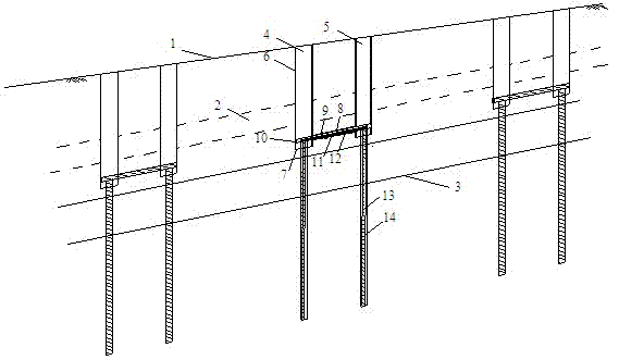
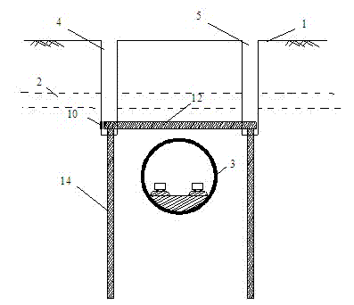
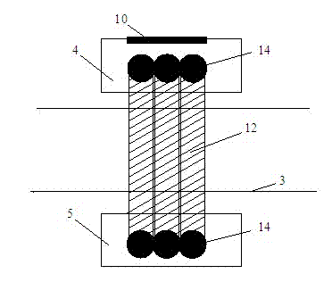
[0029] In the site area below the ground surface 1 containing the liquefiable soil layer 2 and the operating tunnel 3, a method for controlling the floating deformation of the operating tunnel of the liquefaction site under the action of an earthquake, such as Figure 1-3 As shown, it includes starting working well 4, receiving working well 5, underground continuous wall 6, water stop bottom plate 7, culvert pipe 8, culvert pipe grouting pipe 9, top pipe reaction wall 10, top beam reinforcement cage 11, top beam 12 , The cast-in-place pile reinforcement cage 13, and the drilled occluding reinforced concrete cast-in-place pile 14. During the implementation, first measure the line to determine the ground position corresponding to the area of ​​the...


PUM

PropertyMeasurementUnit
Diameteraaaaaaaaaa
Lengthaaaaaaaaaa
Diameteraaaaaaaaaa

Abstract

The invention relates to a method for controlling upward flotation and deformation of a liquefiable ground operating tunnel under the action of an earthquake. The method comprises the following steps: digging vertical work shafts on two sides of the operating tunnel to the crest level of the tunnel; carrying out bored pile construction in the work shafts at the two sides; transversely jacking pipes at the crest level of the tunnel; placing a reinforcement cage in a culvert pipe hole and horizontally pouring concrete to form a top beam of the operating tunnel, wherein an operating tunnel door-shaped control structure is formed by the beam and bored cast-in-place piles on the two sides; binding and fixedly connecting the top beam and the cast-in-place piles by the reinforcement cage; and finally, carrying back filling and compacting the work shafts. The door-shaped control structures are respectively arranged at intervals of 200 m to 500 m in an area with a liquefied layer along the direction of the operating tunnel, so that the linear full-length non-control tunnel is changed into a sectional control structure. The technical method does not influence normal traffic of the tunnel during the construction, does not need to carry out great digging, is low in engineering cost and has low influence on surrounding buildings and the operating tunnel; and the cost for long-term maintenance is reduced and the operation safety is ensured.

Description

Technical field [0001] The invention relates to the technical field of tunnels and underground engineering, in particular to a method for controlling the floating deformation of a tunnel operating at a liquefaction site under the action of an earthquake. It is mainly applicable to technical fields such as the floating deformation control of subways, highways and railway tunnels in the liquefied sand soil foundation under the action of earthquakes. Background technique [0002] With the massive construction and operation of infrastructure such as subway tunnels and river-crossing tunnels, it is inevitable to pass through earthquake-affected areas with liquefied sandy soil layers. Earthquake liquefaction sites can easily cause the floating deformation of underground structures under the action of earthquakes, leading to serious floating deformation and even destruction of the structure. Subway tunnels, highways and railway tunnels are lifeline projects. Improper control will serio...

Claims


Application Information

Patent Timeline
IPC IPC(8): E21D9/00
Inventor 刘汉龙孔纲强陈育民丁选明
Owner HOHAI UNIV
Learn More