Oil return system for centrifugal water-chilling unit

A technology of oil return system and water chiller, which is applied in refrigerators, refrigeration components, compressors, etc., and can solve problems such as high refrigerant content and diluted oil concentration

Active Publication Date: 2013-03-13
CHONGQING MIDEA GENERAL REFRIGERATING EQUIP
View PDF7 Cites 9 Cited by
  • Summary
  • Abstract
  • Description
  • Claims
  • Application Information

AI Technical Summary

Problems solved by technology

[0004] The purpose of the embodiments of the present invention is to provide an oil return system for centrifugal chillers, which aims to solve the problems of high refrigerant content in the return oil and the concentration of diluted oil in the prior art

Method used


Image

  • Oil return system for centrifugal water-chilling unit
  • Oil return system for centrifugal water-chilling unit

Examples


Embodiment Construction

[0015] In order to make the object, technical solution and advantages of the present invention clearer, the present invention will be further described in detail below in conjunction with the accompanying drawings and embodiments. It should be understood that the specific embodiments described here are only used to explain the present invention, not to limit the present invention.

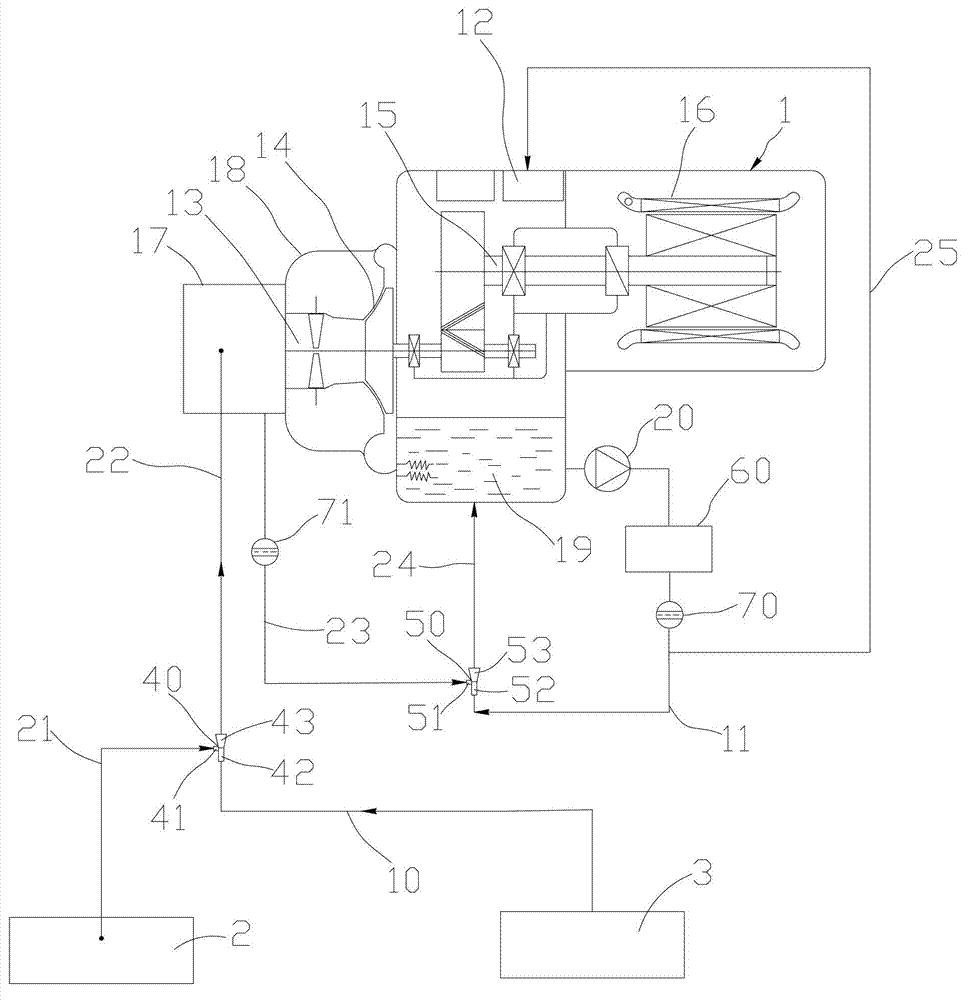
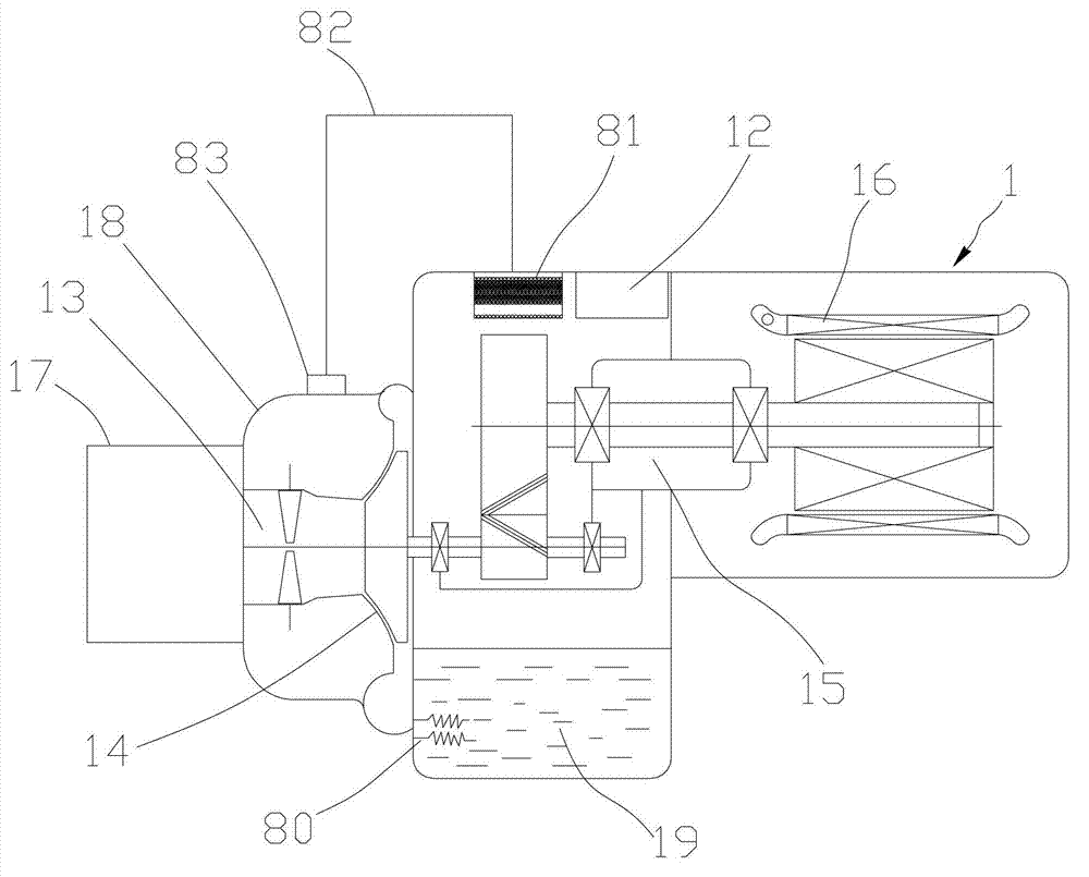
[0016] see figure 1 and figure 2 , the oil return system provided by the embodiment of the present invention is used in a centrifugal chiller. The oil return system includes an evaporator 2 , a condenser 3 and a centrifugal compressor 1 . The centrifugal compressor 1 includes a blade ring assembly 13 , a suction chamber 17 located at the front end of the blade ring assembly 13 and an oil tank 19 for storing lubricating oil.

[0017] The oil return system also includes a high-pressure air pipe 10, a first pipeline 21, a first Venturi nozzle 40, a second pipeline 22, an oil pump 20, a second Vent...


PUM


Abstract

The invention provides an oil return system for a centrifugal water-chilling unit. The oil return system comprises an evaporator, a condenser, a centrifugal compressor, a high-pressure gas pipe, five pipelines, a first Venturi nozzle, an oil pump and a second Venturi nozzle. The centrifugal compressor comprises a blade ring component, a gas suction chamber and an oil tank, wherein the gas suction chamber and the oil tank are arranged at the front end of the blade ring component, one end of the high-pressure gas pipe is connected with a gas suction end of the condenser, and the other end of the high-pressure gas pipe is connected with an ejection end of the first Venturi nozzle; one end of a first pipeline is connected into the evaporator, and the other end of the first pipeline is connected with a leading-in end of the first Venturi nozzle; one end of a second pipeline is connected with a negative pressure end of the first Venturi nozzle, and the other end of the second pipeline is connected into the gas suction chamber of the compressor; one end of a third pipeline is connected with the oil tank, and the other end of the third pipeline is connected with an ejection end of the second Venturi nozzle; the oil pump is connected with a third pipeline; one end of a fourth pipeline is connected with the gas suction chamber of the compressor, and the other end of the fourth pipeline is connected with a leading-in end of the second Venturi nozzle; and one end of a fifth pipeline is connected with a negative pressure end of the second Venturi nozzle, and the other end of the fifth pipeline is connected into the oil tank.

Description

technical field [0001] The invention belongs to the field of air conditioners, and in particular relates to an oil return system for a centrifugal chiller. Background technique [0002] In large centrifugal chillers, the centrifugal compressor is the core component of the entire system, providing power for the entire system cycle. During the operation of the centrifugal compressor, a certain amount of lubricating oil must be injected. The purpose of the lubricating oil is mainly to lubricate, cool, seal, disperse stress, and prevent rust. During the operation of the unit, oil will be mixed into the refrigerant, which will bring two effects. On the one hand, the heat exchange effect of the heat exchanger will be reduced. If there is less and less oil, it may cause the unit to fail to operate normally. Therefore, the oil return system is an essential device for centrifugal chillers. [0003] In the existing oil recovery system design, the refrigerant in the condenser is gene...

Claims


Application Information

Patent Timeline
Patent Type & Authority Applications(China)
IPC IPC(8): F25B31/00
Inventor 夏伦熹代奇彬张斌
Owner CHONGQING MIDEA GENERAL REFRIGERATING EQUIP
Why Eureka
Try Eureka