
Oil return structure of compressor barrel pump

A technology for compressors and compressor units, applied in the field of compressors, which can solve problems such as poor control of the liquid level of the oil-rich layer and ineffectiveness, and achieve the effects of strong practicability, easy maintenance, and scientific and reasonable design

Inactive Publication Date: 2018-01-05
TIANJIN DANHUA HONGYE REFRIGERATION TECH CO LTD
View PDF0 Cites 3 Cited by
  • Summary
  • Abstract
  • Description
  • Claims
  • Application Information

AI Technical Summary

Problems solved by technology

[0004] The disadvantage of the above method is: the liquid level of the oil-rich layer is not easy to control, resulting in poor effect

Method used


Image

  • Oil return structure of compressor barrel pump

Examples


Embodiment Construction

[0011] The present invention will be further described in detail below in conjunction with the accompanying drawings and through specific embodiments.

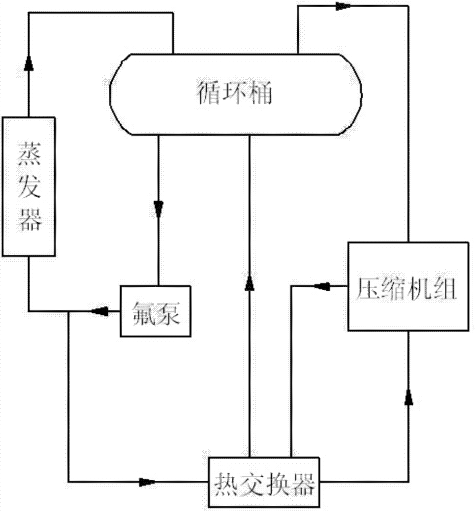
[0012] An oil return structure of a compressor barrel pump, such as figure 1 As shown, it includes a circulation barrel, a compressor unit, a heat exchanger, a fluorine pump and an evaporator which are connected in sequence and form a loop.

[0013] The innovation of the present invention is:

[0014] The outlet end of the fluorine pump is connected to the inlet end of the heat exchanger through a pipeline, and the outlet end of the heat exchanger is connected to the suction end of the compressor unit through a pipeline.

[0015] In this structure, the oil-liquid mixture is sent into the heat exchanger through the pressure of the outlet of the fluorine pump, and the oil-liquid mixture is vaporized through the heat exchanger, and supplied to the suction end of the compressor unit.

[0016] The oil return structure of the pres...


PUM


Abstract

The invention relates to an oil return structure of a barrel pump of a compressor, which comprises a circulation barrel, a compressor unit, a heat exchanger, a fluorine pump and an evaporator which are sequentially connected to form a circuit, and is characterized in that: the outlet end of the fluorine pump passes through a pipe The pipe is connected to the inlet end of the heat exchanger, and the outlet end of the heat exchanger is connected to the suction end of the compressor unit through a pipeline. The design of the oil return structure of the present invention is scientific and reasonable, and the concept is ingenious. The purpose of oil return is achieved by vaporizing the oil through the heat exchanger, which effectively ensures the reliable operation of the entire unit. The oil circuit design of the present invention is simple, easy to maintain, and practical Strong.

Description

technical field [0001] The invention belongs to the technical field of compressors, in particular to an oil return structure of a barrel pump of a compressor. Background technique [0002] The compressor sucks the lower-pressure working medium vapor from the evaporator, raises its pressure, and sends it to the condenser, where it is condensed into a higher-pressure liquid, which becomes a higher-pressure liquid after being throttled by the throttle valve. After the low-pressure liquid is sent to the evaporator, it absorbs heat and evaporates in the evaporator to become a steam with a lower pressure, thereby completing the refrigeration cycle. [0003] Oil plays three roles in the compressor unit: lubrication, sealing, and driving operation. If the oil cannot continue to circulate in the unit, it will not work properly. The traditional method is to collect oil-rich layers and return to the suction end of the compressor working group by the gravity of the liquid. [0004] Th...

Claims


Application Information

Patent Timeline
Patent Type & Authority Applications(China)
IPC IPC(8): F25B31/00
Inventor 肖鹏
Owner TIANJIN DANHUA HONGYE REFRIGERATION TECH CO LTD
Learn More