Suction tool for electric vacuum cleaner and electric vacuum cleaner provided with same

A technology for suction parts and vacuum cleaners, which is applied in the field of electric vacuum cleaners and suction parts for electric vacuum cleaners. It can solve the problems of increased noise such as wind noise, and achieve the effect of improving quietness and reducing noise.

Inactive Publication Date: 2013-03-13
PANASONIC CORP
6 Cites 1 Cited by

AI-Extracted Technical Summary

Problems solved by technology

Then, the turbulent air collides with the air flowing in from the lower surface of the suction chamber 105 in the sucti...

Method used

And, since the suction wind sucked from the suction member 1 is sucked separately from the suction opening 35 and the opening 12a of the suction chamber 12, the amount of the suction wind inside the suction chamber 12 can be reduced, The flow velocity is reduced, so the sound pressure of the wind noise generated by the suction tool 1 can be reduced.
Thus, the air sucked from the main body of the suction piece 1 by the user starting the operation of the electric vacuum cleaner 100 is scattered and flows into the suction chamber 12 from the suction port 35 and the opening 12a, so that the The wind noise generated by the main body of the suction piece 1 sucking air can improve the quietness of the main body of the suction piece 1 .
Thus, the sound-absorbing member can be used to absorb the wind noise generated when the external air inhaled from the suction port 35 passes through the communication passage 39 and the noise generated in the suction chamber, and the silence of the suction piece main body can be further enhanced. sex. In addition, by providing a sound absorption chamber (space portion 40 ) independently of the communication passage 39 in the vicinity of the communication passage 39 , the sound absorption chamber can reduce the wind generated when the outside air sucked in from the suction port 35 passes through the communication passage 39 . Noise can improve the quietness of the main body of the suction piece 1 .
[0035] As shown in FIG. 2 and FIG. 3, a plurality of holes are provided on the upper surface of the rotating brush 15 on the top surface of the suction chamber 12 of the lower member 11, which are used as sound-absorbing holes 37. In addition, an exhaust port portion 38 that communicates the inside of ...

Abstract

Disclosed is a suction tool for an electric vacuum cleaner provided with: a suction tool main body which comprises an opening (12a) in a lower surface, and comprises a suction chamber (12) thereinside that communicates with the opening (12a); and a connection pipe (18) which is attached to the suction tool main body and communicates with the suction chamber (12). An air intake port (35) for taking in external air is provided in the external surface of the suction tool main body, and an air exhaust port (38) for providing communication between the air intake port (35) and the suction chamber (12) is provided inside the suction tool main body. A sound absorption chamber is provided adjacent to but separately from a communication passage (39) for providing communicating between the air intake port (35) and the air exhaust port (38) of the suction tool main body.

Application Domain

Suction nozzlesExhaust-air diffusion

Technology Topic

EngineeringVacuum cleaner

Image

  • Suction tool for electric vacuum cleaner and electric vacuum cleaner provided with same
  • Suction tool for electric vacuum cleaner and electric vacuum cleaner provided with same
  • Suction tool for electric vacuum cleaner and electric vacuum cleaner provided with same

Examples

  • Experimental program(1)

Example Embodiment

[0018] Next, embodiments of the present invention will be described in detail with reference to the drawings.
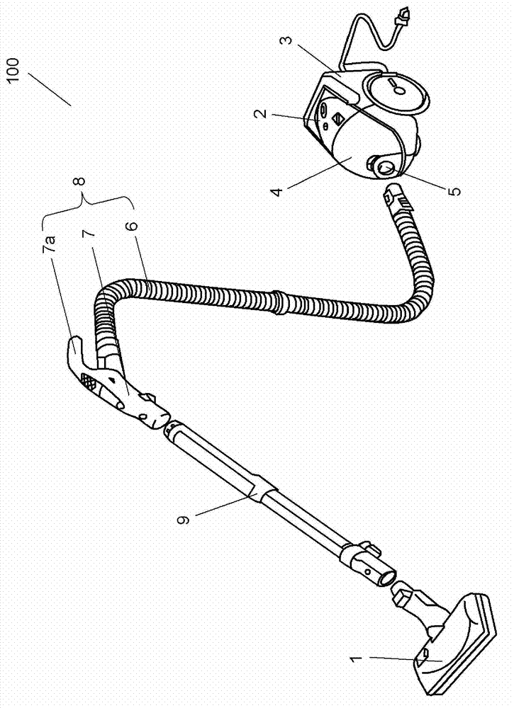
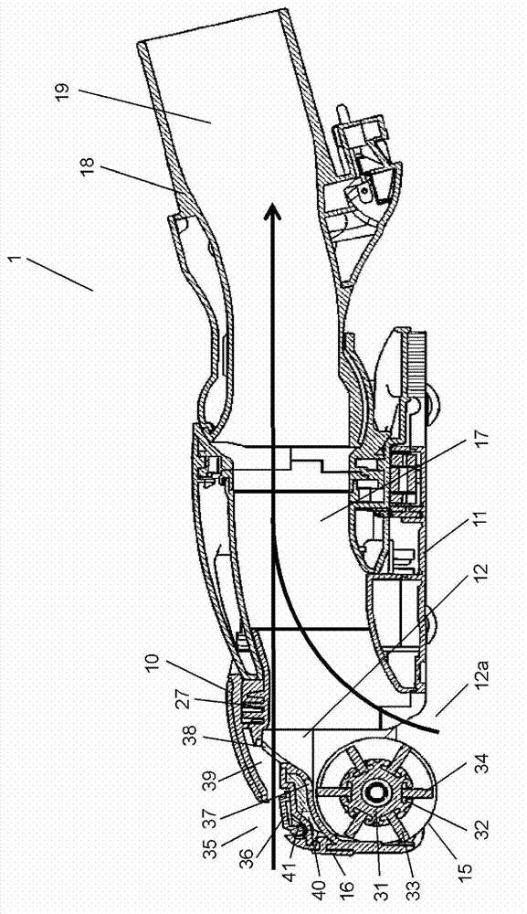
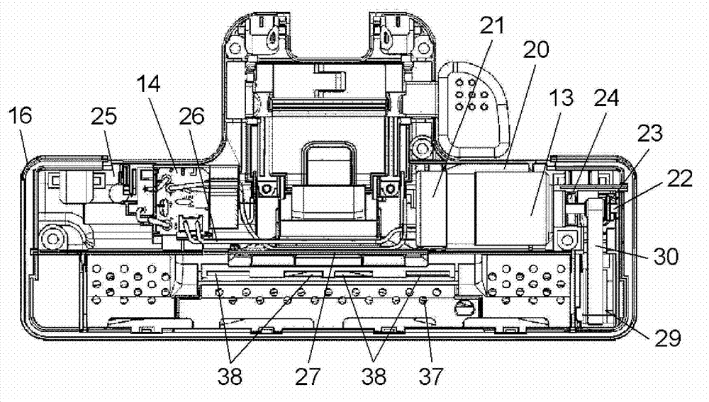
[0019] figure 1 It is a perspective view showing the overall structure of an electric vacuum cleaner having a suction tool for an electric vacuum cleaner in the embodiment of the present invention. figure 2 It is a side cross-sectional view which shows the structure of the suction tool for electric vacuum cleaners in embodiment of this invention. image 3 It is a top view which shows the structure of the state which removed the upper member of the suction tool for vacuum cleaners in embodiment of this invention. In addition, Figure 4 It is a bottom view which shows the structure of the suction tool for electric vacuum cleaners in embodiment of this invention.
[0020] Such as figure 1 As shown, the electric vacuum cleaner 100 has a cleaner body 2, a suction member 1, a hose 8 and an extension pipe 9.
[0021] The suction member 1 sucks dust on the surface to be cleaned. One end of the hose 8 is connected to the cleaner body 2 and the other end is connected to the extension pipe 9. One end of the extension tube 9 is connected with the other end of the hose 8, and the other end of the extension tube 9 is connected with the suction member 1.
[0022] The cleaner body 2 has an electric blower chamber 3 and a dust collecting part 4. The electric blower chamber 3 contains an electric blower for generating suction air. The dust collecting part 4 is arranged on the upstream side of the electric blower chamber 3, and collects the dust sucked in from the suction tool 1 by the suction wind generated by the electric blower.
[0023] In addition, a dust collection port 5 to which one end of the hose part 6 of the hose 8 is connected is provided in the front part of the cleaner body 2.
[0024] The hose 8 has a hose part 6, a hose handle part 7, and a holding part 7a. One end of the hose part 6 is connected to the dust collection opening 5 of the cleaner body 2, and is formed of a flexible material and can be moved flexibly. The hose handle 7 is provided at the other end of the hose 6, and an electric device for controlling the cleaner body 2 and the suction tool 1 is built-in. The holding portion 7a is provided on the hose handle portion 7 for the user to hold when using the electric vacuum cleaner 100.
[0025] The extension tube 9 connects the hose handle 7 and the suction member 1, and is formed of a rigid material. A power supply line for supplying power to the suction tool 1 is built in the extension tube 9.
[0026] Such as figure 2 As shown, the suction member 1 is composed of an upper member 10 forming the upper part of the main body of the suction member 1, a lower member 11 constituting the lower part of the main body of the suction member 1, and a rear part of the suction member 1 in a movable manner. The connecting pipe 18 which is connected to the extension pipe 9 in the center is constituted.
[0027] The suction tool 1 includes a rotating brush 15 that sweeps up dust on the surface to be cleaned, a motor 13 that drives the rotating brush 15 to rotate, and a control circuit 14 that controls the motor 13. In addition, a bumper 16 is provided on the outer circumference of the suction member 1. When the upper member 10 and the lower member 11 are combined, the motor 13, the control circuit 14, the rotating brush 15 and the buffer 16 are sandwiched and held by the upper member 10 and the lower member 11.
[0028] A suction chamber 12 having an opening 12a that opens downward and a connection passage 17 that communicates the suction chamber 12 and the connection pipe 18 are provided in the lower member 11. In the suction chamber 12, a rotating brush 15 for sweeping dust on the surface to be cleaned is arranged so as to face the opening 12a. In addition, a dust collection passage 19 that communicates with the suction chamber 12 via a connection passage 17 is provided inside the connection pipe 18.
[0029] Such as image 3 As shown, the lower member 11 is formed with chambers divided left and right by the connecting passage 17. One chamber is used as the motor chamber 20 and the other chamber is used as the circuit chamber 25. In addition, such as Figure 4 As shown, in the vicinity of the four corners of the bottom surface of the lower member 11, for the purpose of preventing the lower member 11 from directly contacting the surface to be cleaned and not scratching the surface to be cleaned, rollers 28 for traveling are provided.
[0030] Such as image 3 As shown, a motor 13 that drives the rotating brush 15 to rotate is built in the motor chamber 20. The motor 13 is vibration-isolated and supported on the lower member 11 via the vibration-isolating rubber 21. A motor shaft 22 is provided at the center of the motor 13, and a first pulley 23 having a tooth profile and a flange in one direction is provided at the end of the motor shaft 22. In addition, a bearing portion 24 that holds the motor shaft 22 on the lower member 11 is provided between the motor 13 and the first pulley 23.
[0031] A control circuit 14 for controlling the motor 13 is provided in the circuit room 25. The control circuit 14 is held on the lower member 11. The electric motor 13 and the control circuit 14 are connected by a connecting wire 26, and the connecting wire 26 is arranged on a bridge body 27 provided in the upper part of the connecting passage 17.
[0032] The rotating brush 15 has a base material 31, a plurality of grooves 32, a fur brush 33, and a peripheral brush (Japanese: Zhou Bilaxi) 34. The base material 31 is a rigid body formed of aluminum, foamable resin, or the like. The plurality of grooves 32 are formed in a spiral shape in the longitudinal direction of the base 31 and open toward the outer periphery of the base 31. The brush 33 has a function of wiping a surface to be cleaned, such as a wooden floor. The peripheral brush 34 has a function of peeling dust from the cleaned surface such as a carpet. The fur brushes 33 and the peripheral brushes 34 are alternately inserted and fixed to the base material 31.
[0033] Such as image 3 As shown, the end of the rotating brush 15 on the motor 13 side is provided with a second pulley 29 having the same tooth profile as the first pulley 23 and a different number of teeth. At a position of the second pulley 29 opposite to the position where the flange portion of the first pulley 23 is provided, a flange portion is provided in the same manner as the first pulley 23. The first pulley 23 and the second pulley 29 are connected by a timing belt 30 and are configured to transmit the power of the electric motor 13 to the rotating brush 15.
[0034] Such as figure 2 As shown, the upper member 10 is provided with a suction port 35 communicating the inside of the upper member 10 with the external environment at the front of the suction member 1 in a manner of communicating with the connecting passage 17. In addition, a lid 36 that opens and closes the suction port 35 is provided in the suction port 35. Accordingly, when the operation of the electric vacuum cleaner 100 is stopped, dust is not released from the suction port 35 to the external environment, and the suction tool 1 for the clean electric vacuum cleaner 100 can be provided.
[0035] Such as figure 2 with image 3 As shown, a plurality of holes are provided on the upper surface of the rotating brush 15 on the top surface of the suction chamber 12 of the lower member 11 to serve as silencer holes 37. In addition, an exhaust port 38 that communicates the inside of the upper member 10 with the suction chamber 12 is provided. The exhaust port 38 is also provided so as to communicate with the connection passage 17 in the same manner as the intake port 35. In addition, the intake port 35 and the exhaust port 38 communicate with each other via a communication passage 39. Preferably, a plurality of exhaust ports 38 are provided. With this structure, the main body of the suction member 1 has a sound absorption effect, and the strength of the main body of the suction member 1 can be improved compared with a structure in which a larger exhaust port 38 is provided.
[0036] In addition, the intake port 35 and the exhaust port 38 are preferably provided so that the communication passage 39 is substantially parallel to the surface to be cleaned. With this structure, the vector direction of the flow of external air sucked in from the suction port 35 and passing through the communication passage 39 can be made to coincide with the vector direction of the flow of wind flowing in the suction chamber 12, and it is possible to sufficiently suppress the flow in the suction chamber 12. The occurrence of turbulence inside can further improve the quietness of the main body of the suction tool 1.
[0037] On the lower side of the communication passage 39, a space 40 as a sound absorption chamber is provided in the upper part of the suction chamber 12, and a plurality of muffler holes 37 connecting the space 40 and the suction chamber 12 are provided. In addition, a sound absorbing member 41 having a sound absorbing effect is provided in the space portion 40 so as to block the silencing hole 37.
[0038] Thereby, the sound absorbing member can absorb wind noise generated when the external air sucked in from the suction port 35 passes through the communication passage 39 and noise generated in the suction chamber, and the quietness of the suction tool body can be further enhanced. In addition, by providing the sound absorption chamber (space portion 40) in the vicinity of the communication passage 39 independently of the communication passage 39, the sound absorption chamber can be used to reduce wind generated when the external air sucked in from the suction port 35 passes through the communication passage 39. Noise can improve the quietness of the main body of the suction device 1.
[0039] With regard to the suction tool for the electric vacuum cleaner 100 configured as described above, its operation and effect will be described below.
[0040] First, when the user starts the operation of the cleaner body 2 in order to clean the surface to be cleaned, the electric blower generates suction air. When suction air is generated by the electric blower, external air flows in from the opening 12a and the suction port 35 of the suction chamber 12 through the hose 8, the extension pipe 9, the dust collection passage 19, and the connection passage 17. In addition, the power supplied from the cleaner body 2 is supplied to the control circuit 14 and the motor 13 through the extension pipe 9. As a result, the motor 13 rotates, and the rotating brush 15 is driven by the timing belt 30.
[0041] As the rotating brush 15 in the suction chamber 12 rotates, the dust on the surface to be cleaned is released from the ground under the action of the fur brush 33 and the peripheral brush 34. The dust is collected by the suction air flowing into the suction chamber 12, and is collected in the dust collecting part 4 of the cleaner body 2 through the connection passage 17, the dust collecting passage 19, the extension pipe 9 and the hose 8. In addition, the suction air reaching the connecting passage 17 from the opening 12 a of the suction chamber 12 mainly constitutes this flow path passing through the lower side of the suction chamber 12. In addition, the rotating sound generated by the fur brush 33 and the peripheral brush 34 passes through the muffler hole 37 and reduces the sound pressure by the sound absorbing member 41, so that it can be muted. That is, the sound absorption chamber (space part 40) absorbs the rotating sound of the rotating brush.
[0042] Next, the intake air flowing in from the intake port 35 first opens the lid 36, passes through the communication passage 39 and reaches the exhaust port 38, and becomes the wind flowing on the upper side of the intake chamber 12. The intake air flowing in from the intake port 35 passes through fewer steps, obstacles, etc., before it flows into the connecting passage 17, and there is no unnecessary step or the like after reaching the connecting passage 17. Thus, even when the suction air flowing in from the suction port 35 merges with the suction air sucked in from the lower surface of the suction chamber 12, the generation of turbulence in the suction chamber 12 can be sufficiently suppressed. The connection pipe 18 Flows smoothly inside. Therefore, the wind noise inside the suction tool 1 can be reduced.
[0043] In addition, since there are no obstacles such as sound-absorbing members in the communication passage 39 between the external air sucked in from the suction port 35 and before reaching the suction chamber 12, it is possible to sufficiently suppress the passage from the suction port 35. The inhaled external air diverges due to obstacles such as a sound absorbing member, and turbulence is generated in the external air passing through the communication passage 39.
[0044] Furthermore, since the suction air sucked from the suction tool 1 is drawn separately from the suction port 35 and the opening 12a of the suction chamber 12, the amount of suction air inside the suction chamber 12 can be reduced and the flow velocity can be reduced. Therefore, the sound pressure of wind noise generated by the suction tool 1 can be reduced.
[0045] As a result, the air sucked from the main body of the suction tool 1 when the user starts the operation of the electric vacuum cleaner 100 is dispersed from the suction port 35 and the opening 12a into the suction chamber 12, so that the air from the suction tool can be reduced. The wind noise generated by the main body inhaling air can improve the quietness of the main body of the suction tool 1.
[0046] Furthermore, since it is possible to sufficiently suppress the occurrence of turbulence in the external air passing through the communication passage 39, it is possible to sufficiently suppress the occurrence of turbulence in the external air passing through the communication passage 39 and the air sucked in from the opening 12a in the suction chamber 12. At the time of collision, turbulence is generated in the suction chamber 12. Therefore, noises such as wind noise generated in the suction chamber 12 can be reduced, and the quietness of the main body of the suction tool 1 can be improved.
[0047] As described above, in the present embodiment, the upper part of the suction chamber 12 is provided with a space 40 as a sound absorption chamber surrounded by the lower member 11 and the upper member 10 independently of the communication passage 39. In addition, a sound absorbing member 41 is arranged in the space 40. As a result, the sound pressure of the noise value generated by the suction tool 1 can be reduced, and silence can be achieved.
[0048] Therefore, by using the suction tool 1 in the present embodiment, it is possible to provide an electric vacuum cleaner 100 that can reduce noise during cleaning operations and is highly silent.
[0049] Industrial availability
[0050] As described above, according to the present invention, since it is possible to provide a suction tool for an electric vacuum cleaner characterized by being silent, and an electric vacuum cleaner having the suction tool for an electric vacuum cleaner, it can be used as a household appliance using the suction tool for an electric vacuum cleaner. Electric vacuum cleaners and industrial electric vacuum cleaners are useful.

PUM

no PUM

Description & Claims & Application Information

We can also present the details of the Description, Claims and Application information to help users get a comprehensive understanding of the technical details of the patent, such as background art, summary of invention, brief description of drawings, description of embodiments, and other original content. On the other hand, users can also determine the specific scope of protection of the technology through the list of claims; as well as understand the changes in the life cycle of the technology with the presentation of the patent timeline. Login to view more.

Similar technology patents

Emission control apparatus

InactiveUS20020106312A1reduce gas emissionreduce noise
Owner:CLEAN AIR POWER

Friction type adjusting line delivery system

Owner:MIRACLE AUTOMATION ENG CO LTD

System and method for reducing influence of fluid excitation vibration on ship seawater system

ActiveCN109895947AWeaken the impactimprove quietness
Owner:NO 719 RES INST CHINA SHIPBUILDING IND

Noise reducing equipment

InactiveUS20050258000A1reduce noise
Owner:YANO HIROSHI +1

Car vertical column structure

ActiveCN107512315AImproved crashworthiness and stiffness strengthImprove quietness
Owner:BYD CO LTD

Absolute angle detecting device

InactiveUS20060054797A1improve quietness
Owner:ALPS ALPINE CO LTD

Classification and recommendation of technical efficacy words

  • Improve quietness
  • reduce noise

Car vertical column structure

ActiveCN107512315AImproved crashworthiness and stiffness strengthImprove quietness
Owner:BYD CO LTD

Absolute angle detecting device

InactiveUS20060054797A1improve quietness
Owner:ALPS ALPINE CO LTD

System and method for reducing influence of fluid excitation vibration on ship seawater system

ActiveCN109895947AWeaken the impactimprove quietness
Owner:NO 719 RES INST CHINA SHIPBUILDING IND

Liver subsection method based on CT image and system thereof

InactiveCN101425186Areduce noiseavoid blur
Owner:HUAZHONG UNIV OF SCI & TECH

Noise reduction device

ActiveUS20100014683A1reduce noisehigh quality
Owner:PANASONIC CORP

Automatic image capture

ActiveUS20110170740A1reduce noiseenhance edge
Owner:NORTHWEST IP LLC +1
Why Eureka
Try Eureka