Door mirror

a door mirror and mirror body technology, applied in the field of door mirrors, can solve the problems of large gap between the base stand and the door mirror body, risk of quietness deterioration, etc., and achieve the effects of preventing the falling off of the camera cover, reducing the risk of noise, and simple door mirror structur

Inactive Publication Date: 2010-08-05
MURAKAMI CORP
View PDF5 Cites 10 Cited by
  • Summary
  • Abstract
  • Description
  • Claims
  • Application Information

AI Technical Summary

Benefits of technology

[0011]According to such constitution, the edge part forming a through-hole of the door mirror body enters into the slot portion of the camera cover, and moreover the door mirror body is sandwiched with resilient force between the first abutting surface and the second abutting surface formed in a wall surface of the slot portion. Consequently, falling-off of the camera cover is prevented and the attachment of the camera cover is achieved without screws and adhesive agent, and because of this, structure of the door mirror can become simple.
[0012]In addition, it is preferable that a bracket is further provided which is disposed inside of the door mirror body to fix the camera to the door mirror body, and the second abutting surface is pressed onto the inner surface of the door mirror body by the bracket. According to such constitution, the second abutting surface of the camera cover can be pressed onto the inner surface of the door mirror body by utilizing a bracket for fixing the camera to the door mirror body, and therefore by strengthen the pressing force, the camera cover can be fixed firmly to the door mirror body so that falling-off of the camera cover can be further prevented.

Problems solved by technology

However, in the conventional door mirror, it is difficult to cause the camera base stand made of metal to adhere tightly to the resin door mirror body accurately, and a large gap between the base stand and the door mirror body tends to be generated.
Consequently, the gap easily generates wind noise while a vehicle is running and there is a risk of quietness deterioration.

Method used


Image

  • Door mirror
  • Door mirror
  • Door mirror

Examples


Embodiment Construction

[0019]Hereinafter, preferred embodiments of the door mirror according to the present invention will be described in detail referring to the drawings.

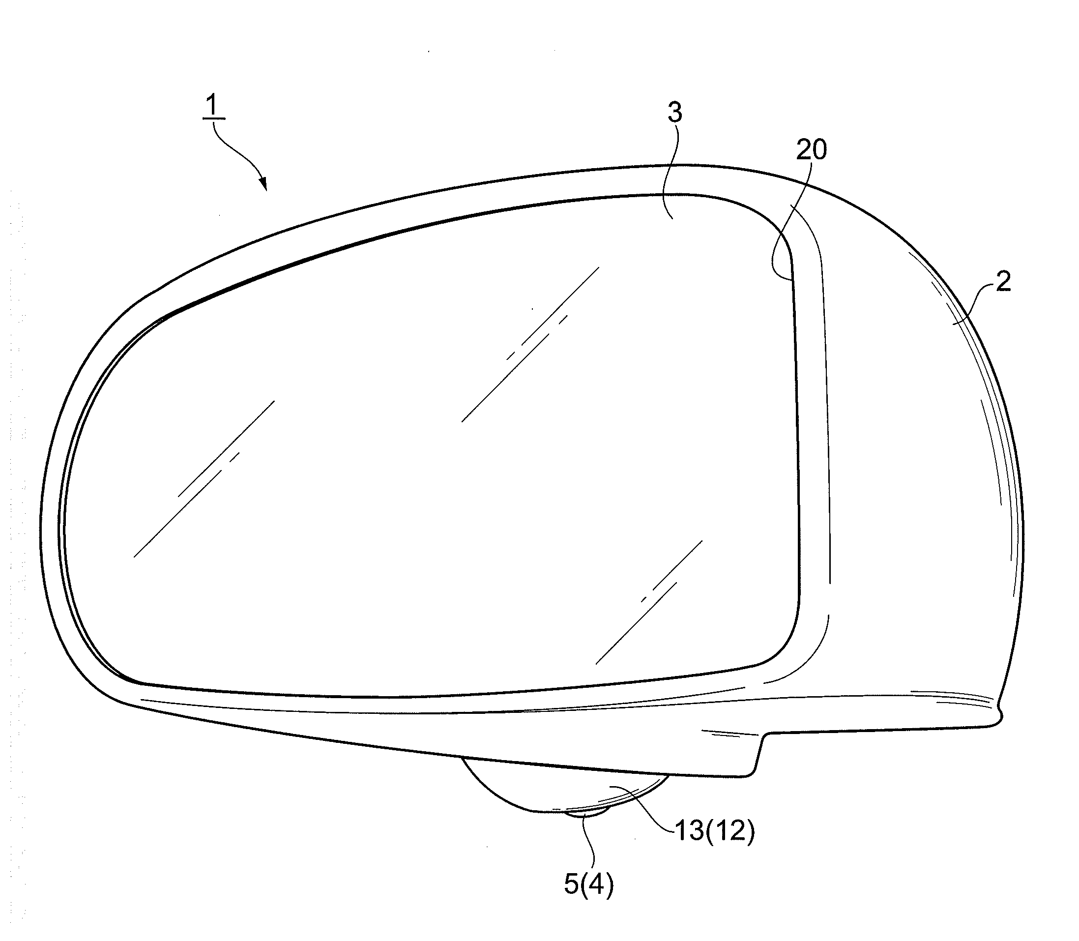
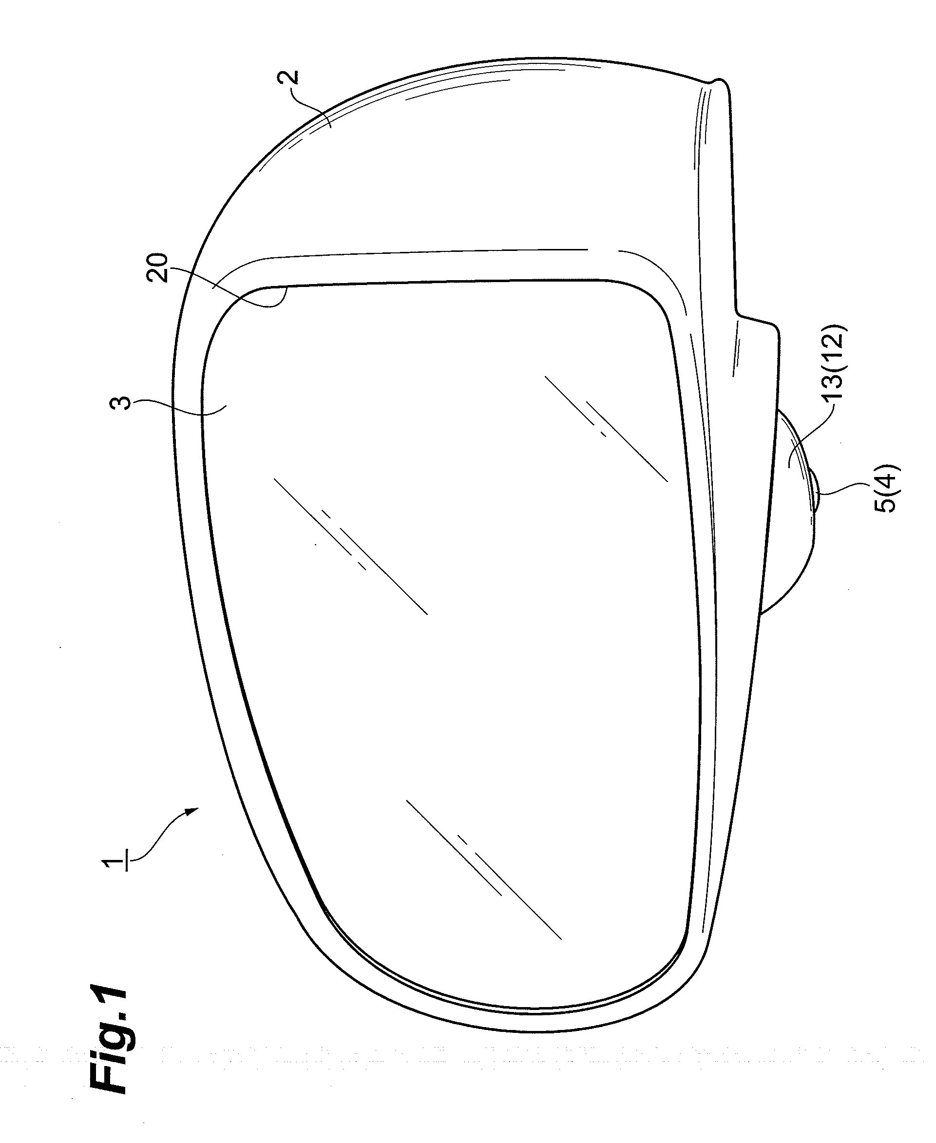
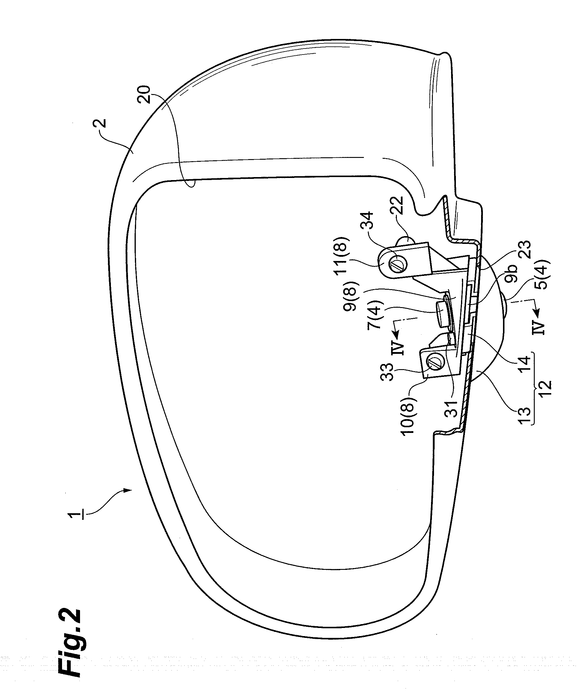
[0020]As shown in FIGS. 1 to 3, the door mirror 1 includes a resin door mirror body 2 which is fixed to the door panel (not shown) of the front side of a vehicle. The door mirror body 2 is formed in a bowl shape which has an opening part 20 opened toward the rear side of the vehicle. In the door mirror body 2, a plate-shaped reflection mirror 3 is disposed so that the opening part 20 is closed. In addition, an actuator for driving a mirror (not shown) to change mirror surface angle of the reflection mirror 3 is provided in the door mirror body 2.

[0021]In a lower surface part of the door mirror body 2, a waterproof camera 4 for checking the side of the vehicle which is in a blind spot from a driver is incorporated. This camera 4 comprises lens part 5 disposed at the front side, a substantially rectangular-shaped camera body 6 having buil...


PUM


Abstract

A door mirror which includes a camera for checking the side of a vehicle which is in a blind spot of a driver, has a door mirror body having a through hole formed for lens side part of the camera to be inserted therein, and a camera cover having an opening part for exposing the lens part formed, and the camera cover has the first abutting surface which abuts on the outer surface of the door mirror body with elasticity.

Description

CROSS-REFERENCE TO RELATED APPLICATION[0001]The disclosure of Japanese Patent Application No.JP2009-19918 filed on Jan. 30,2009 including the specification, drawings and abstract is incorporated herein by reference in its entirety.BACKGROUND OF THE INVENTION[0002]1. Field of the Invention[0003]The present invention relates to a door mirror, which includes a camera for checking the side of a vehicle which is in a blind spot from a driver.[0004]2. Related Background of the Invention[0005]As a technical art in this field heretofore, there has been Japanese Unexamined Patent Application Publication No. 2007-137286. The door mirror described in the patent document comprises a resin door mirror body which is bowl-shaped, and a mirror disposed in an opening part of the door mirror body. The door mirror includes a metallic camera base stand which is attached on an outer surface of the door mirror body and has a sphere-shaped convex part protruding downward, and a camera having a substantial...

Claims


Application Information

Patent Timeline
Patent Type & Authority Applications(United States)
IPC IPC(8): G03B17/48
CPCB60R1/12B60R2011/0033B60R2001/1253B60R11/04
Inventor WATANABE, ATSUSHI
Owner MURAKAMI CORP
Why Eureka
Try Eureka